Soft tip guiding catheter and method of fabrication

a technology of soft tip and catheter shaft, which is applied in the direction of catheters, applications, diagnostics, etc., can solve the problems of affecting the concentricity, stiffness, and kink resistance of the catheter shaft, and causing the danger of puncturing or otherwise damaging the vessel

Inactive Publication Date: 2001-06-12
MEDTRONIC INC
View PDF41 Cites 151 Cited by
  • Summary
  • Abstract
  • Description
  • Claims
  • Application Information

AI Technical Summary

Problems solved by technology

Stiffness or rigidity in the catheter tip poses the danger of puncturing or otherwise damaging a vessel as it twists through the vascular system.
The trend toward thin side wall catheters of less than 0.3 mm wall thickness and a softer distal tip results, however, in a substantially weaker bond between the distal soft tip and the catheter shaft.
A problem which arises with these approaches is that the lap joints or butt joints which bond the catheter shaft, transition segment, and distal soft tip are attained through substantial pressure and / or heat which can have the adverse effects on the concentricity, stiffness, and kink resistance of the catheter shaft.
The exposed braid makes the catheter body rough or irregular at the junction and the thinning can weaken the side wall.

Method used


Image

  • Soft tip guiding catheter and method of fabrication
  • Soft tip guiding catheter and method of fabrication
  • Soft tip guiding catheter and method of fabrication

Examples


Embodiment Construction

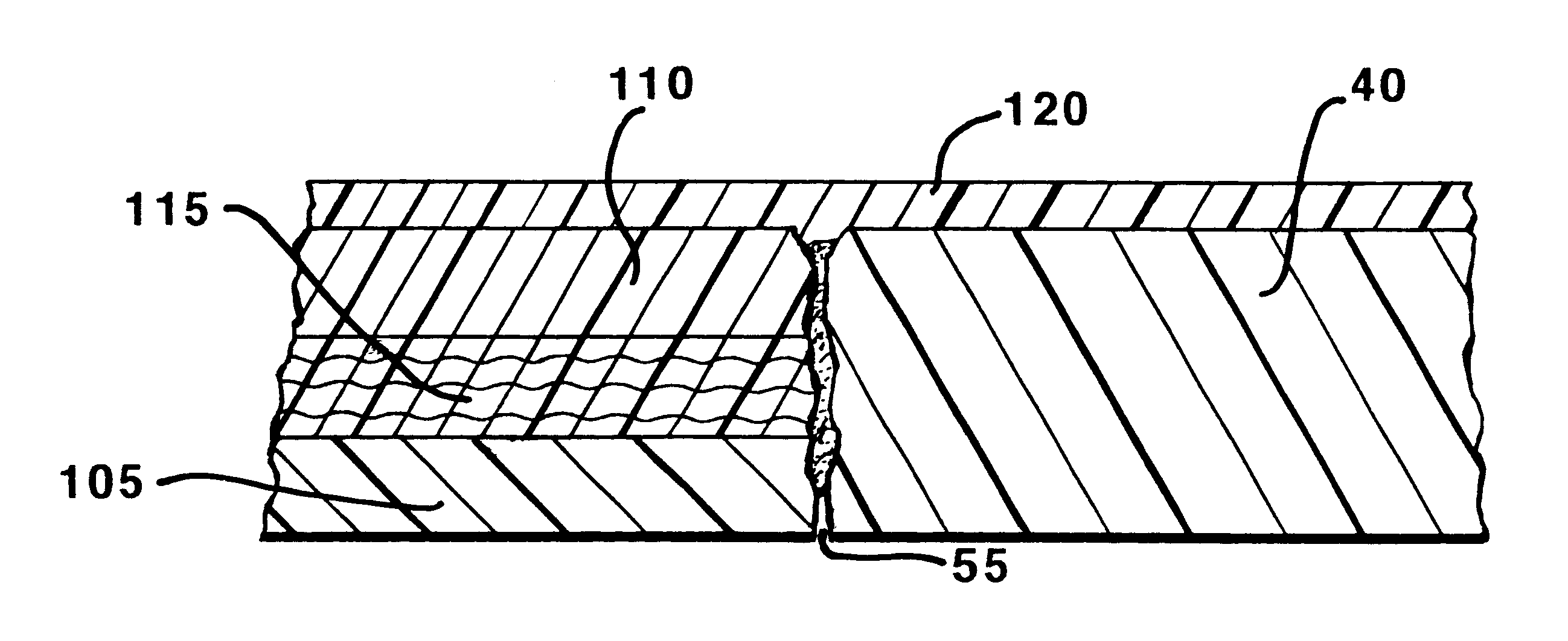
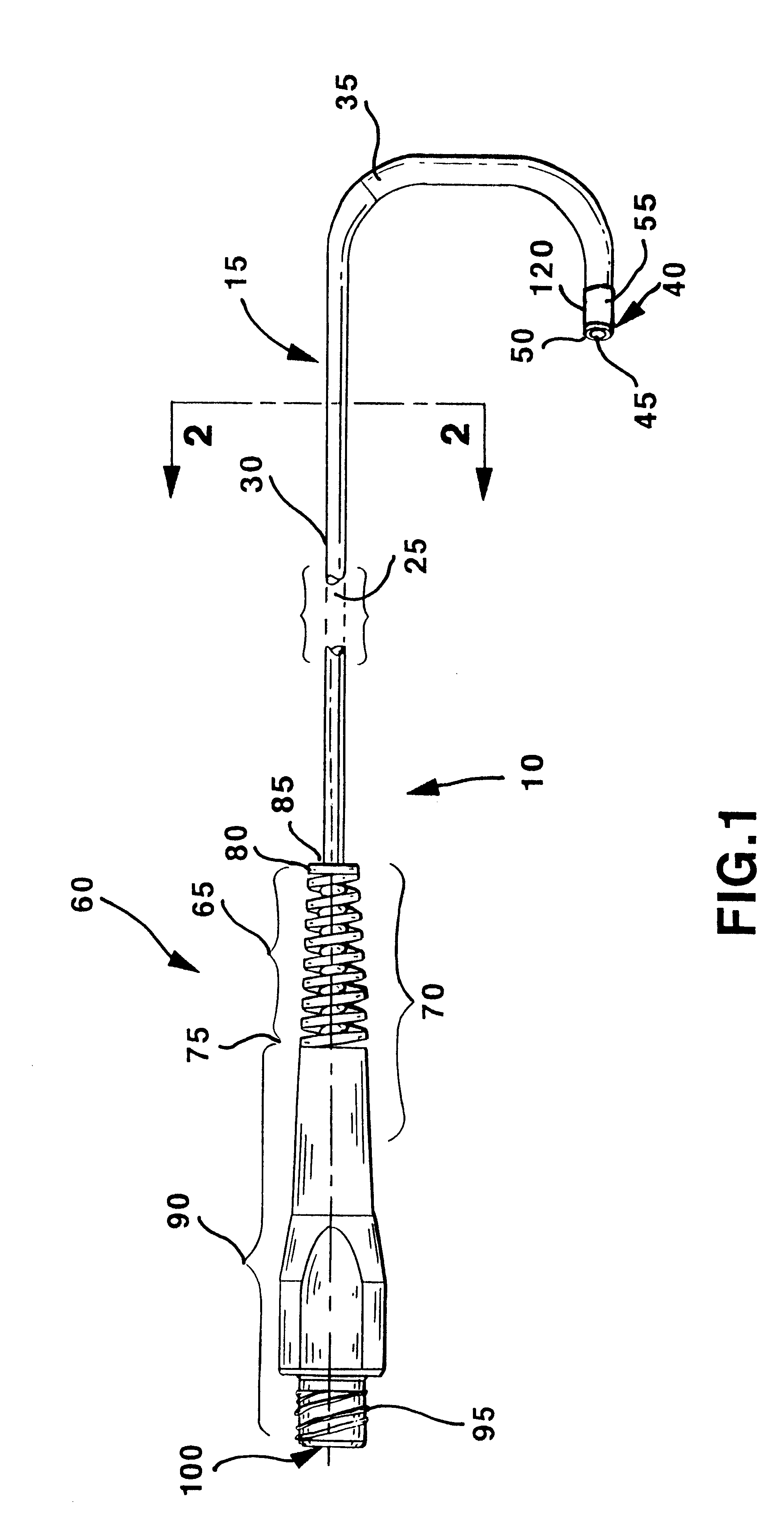
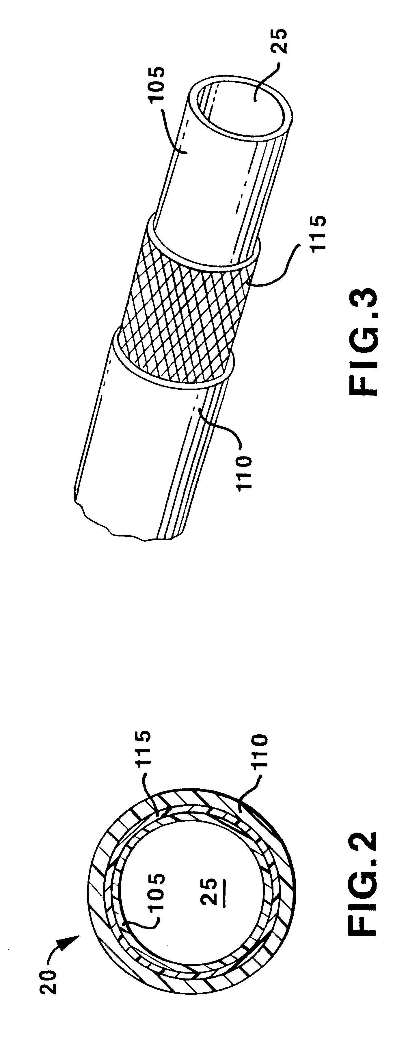
The present invention provides an improved construction for catheters of the type having an elongated catheter body and catheter hub at the catheter body proximal end with at least one catheter lumen extending through the catheter hub and body and to a catheter body distal end thereof. The catheter body is formed of a catheter shaft having a catheter shaft proximal end coupled to the catheter hub and of a relatively short and tubular distal soft tip coupled to the catheter shaft distal end. Such constructions are particularly useful for forming medical vascular catheters in a wide range catheter body lengths and outer diameters. Such catheters include small diameter vascular catheters, having catheter body outside diameters of 4 mm (12 F) preferably below 2.67 mm (8 F), and frequently as small as 1 mm (3 F), and below, such as those used in neurological diagnostic and interventional procedures. Such small diameter vascular catheters will also be useful for other procedures, such as ...


PUM

PropertyMeasurementUnit
wall thicknessaaaaaaaaaa
thicknessaaaaaaaaaa
ultimate tensile strengthaaaaaaaaaa

Abstract

The present invention relates to medical vascular catheters adapted to be inserted into a blood vessel from an incision through the skin of a patient for introducing ther devices or fluids for diagnostic or therapeutic purposes, and particularly to an improved distal soft tip or segment attachment with a relatively stiff proximal catheter shaft. A tubular sleeve is bonded through the application of pressure and heat to a distal portion of the catheter shaft and a proximal portion of the distal segment of soft distal tip bridging the attachment junction. In the preferred method, the catheter shaft distal end is aligned with the distal segment or soft tip proximal end and the sleeve is fitted over the attachment junction. A heat shrink tube is fitted over the sleeve and adjoining portions of the catheter shaft and the distal segment or distal soft tip and heat is applied. The shrinkage force of the heat shrink tube over the assembly of the tubular sleeve overlying and bridging the attachment junction and the applied heat melts and force the materials of the tubular sleeve and the catheter shaft and the distal segment or distal soft tip together to fill interstitial spaces of the attachment junction and reduces the outer diameter of the sleeve. The heat shrink tube is removed after the assembly cools and solidifies. Preferably, the catheter shaft distal end and the soft tip or intermediate segment proximal end are each formed with a like plurality of ungular cut sections that are complementary in shape to one another, whereby the ungular cut sections are aligned with and mated together along the attachment junction.

Description

The present invention relates to medical vascular catheters adapted to be inserted into a blood vessel from an incision through the skin of a patient for introducing other devices or fluids for diagnostic or therapeutic purposes, and particularly to an improved distal soft tip or segment attachment with a relatively stiff proximal catheter shaft.Catheters are tube-like medical instruments that are inserted into a body cavity organ or blood vessel for diagnostic or therapeutic reasons. Medical vascular catheters are particularly designed for insertion into the vasculature and are available for a wide variety of purposes, including diagnosis, interventional therapy, drug delivery, drainage, perfusion, and the like. Medical vascular catheters for each of these purposes can be introduced to numerous target sites within a patient's body by guiding the catheter through an incision made in the patient's skin and a blood vessel and then through the vascular system to the target site.Medical...

Claims


Application Information

Patent Timeline
Patent Type & Authority Patents(United States)
IPC IPC(8): A61M25/00A61M25/08A61M25/088A61M25/16
CPCA61M25/0014A61M25/001A61M25/0054A61M25/0069A61M2025/0081
Inventor BENJAMIN, THIERRY
Owner MEDTRONIC INC
Why Eureka
Try Eureka