Method for transmitting digital data impulses

Inactive Publication Date: 2001-06-19
TELEFUNKEN PATENTVERWERTUN GMBH +1
View PDF12 Cites 3 Cited by
  • Summary
  • Abstract
  • Description
  • Claims
  • Application Information

AI Technical Summary

Benefits of technology

to avoid the need for using the time duration between the beginning and end of a single synchronization or data impulse as the base for deriving a clock frequency and / or an acquisition frequency;

Problems solved by technology

However, a permanent follow-up or intermediate synchronization is not possible with a conventional bit sequence of digital data impulses having unknown impulse levels.
A transformation of digital data impulses into a pulse width modulation, however, is rather subject to a substantial effort and expense and is thus not feasible for all applications.
However, Manchester encoding cannot be employed in certain prior art methods that transmit digital data impulses to a data acquisition signal generator (DASG).
Hence, in the above described conventional methods it is not possible to use Manchester encoding.

Method used


Image

  • Method for transmitting digital data impulses
  • Method for transmitting digital data impulses
  • Method for transmitting digital data impulses

Examples


Embodiment Construction

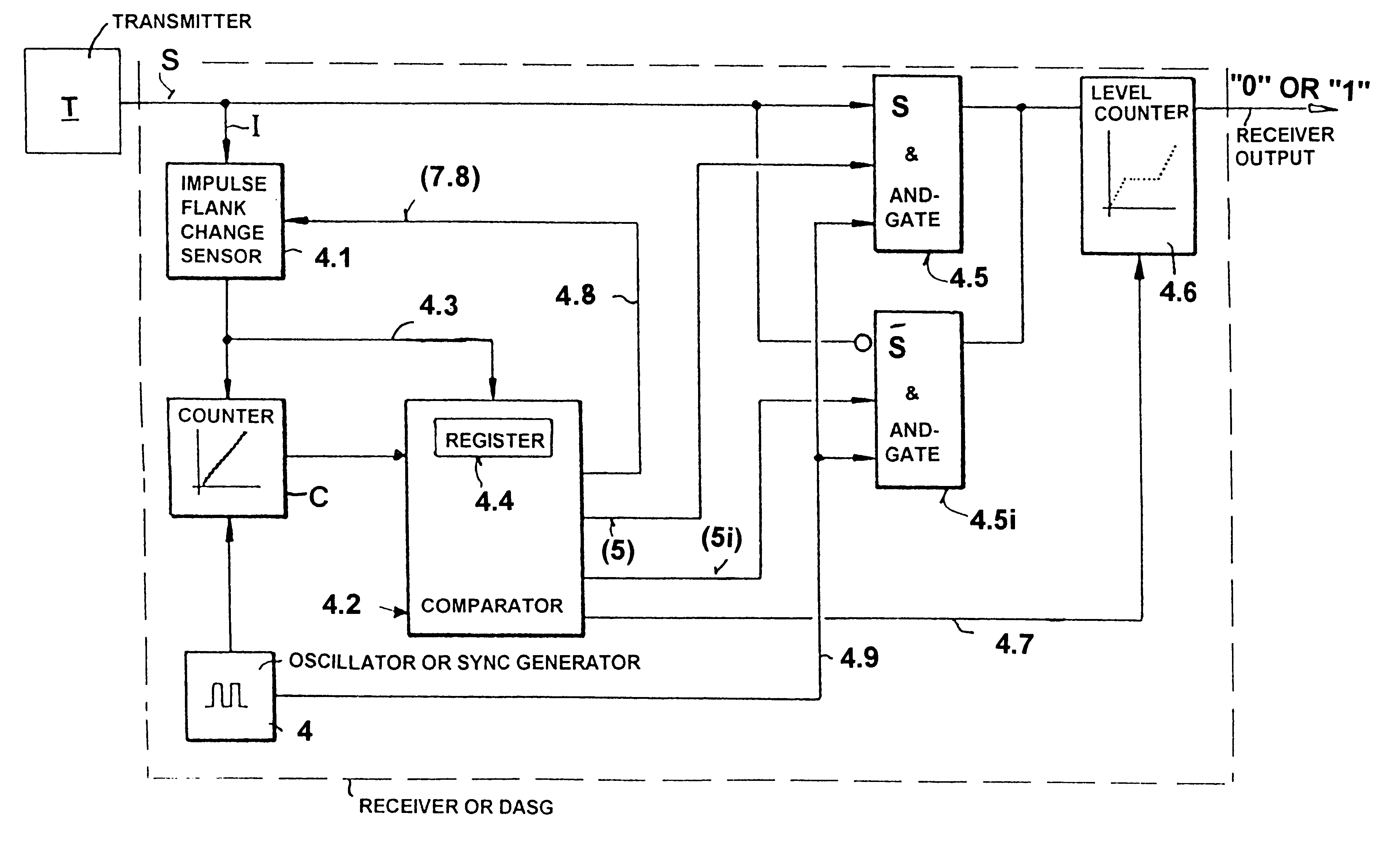
The term synchronization a used herein has been shortened to sync, e.g. sync frequency. The following definitions for the various frequencies here involved are used in this text. A sync frequency is derived from a sync pulse duration. A data frequency is derived from a data pulse duration. Preferably the sync frequency and the data frequency are identical to each other. A stepping frequency is generated by an oscillator 4 to provide stepping pulses SP. A current sync frequency is derived from at least one count of steeping pulses. A current sync frequency becomes a current accepted sync frequency if the current sync frequency meets certain criteria as described below. A data acquisition frequency corresponds to a current accepted sync frequency.

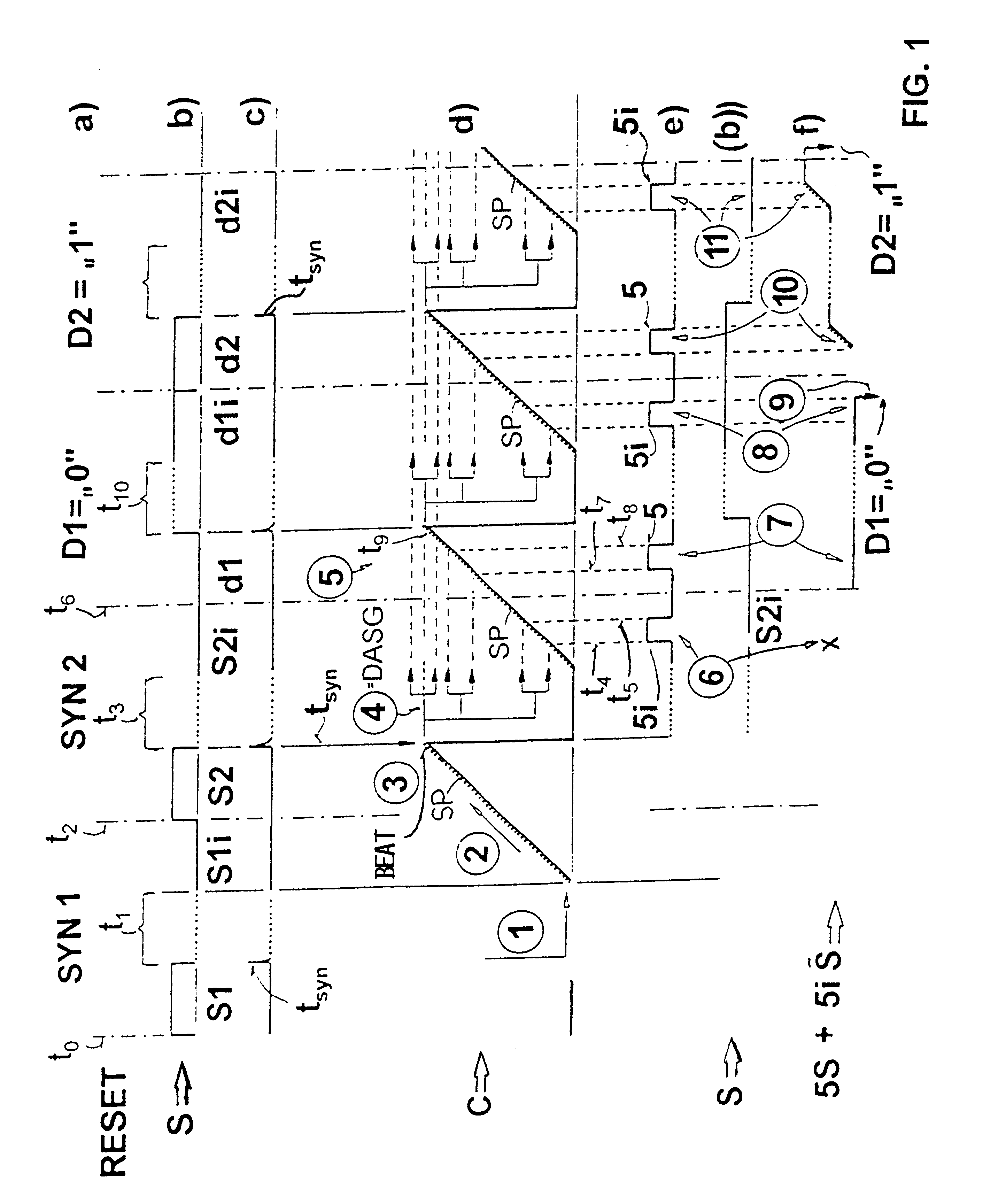
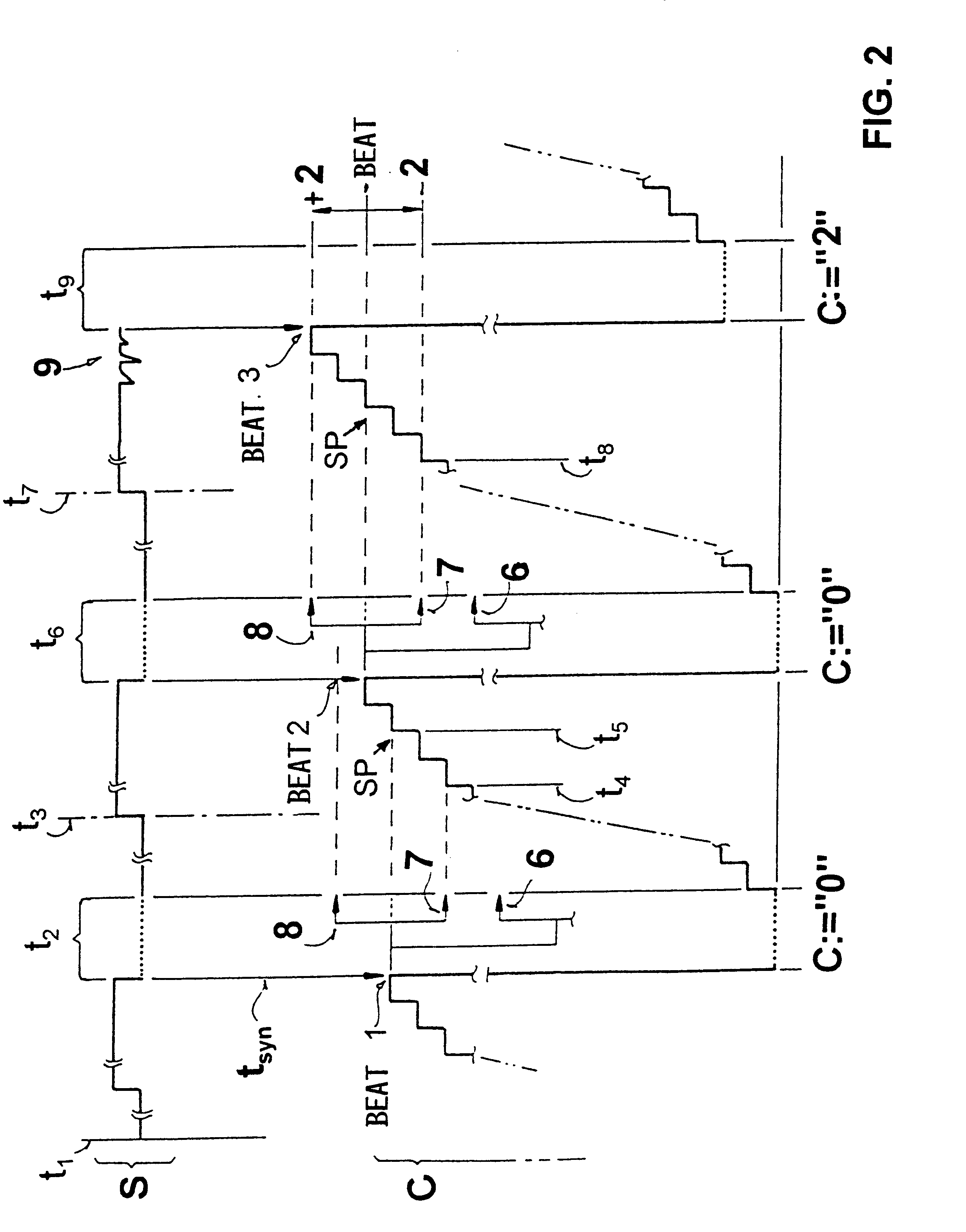
FIG. 1 shows the time sequence diagrams 1a to 1f with reference to a common time base on an abscissa which is not shown in detail. The time base shows a virtual interruption in the center of each impulse. This virtual interruption of an impul...


PUM


Abstract

Before digital data impulses are transmitted from a transmitter to a receiver that includes a data acquisition signal generator, at least one synchronizing impulse (syn1, . . . ) is transmitted for synchronizing the transmitter with the receiver with regard to a sync frequency that is repeatedly updated to provide a current accepted sync frequency. The at least one synchronizing impulse and the data impulses are Manchester encoded which combines timing (synchronizing) and data signals. An impulse flank change occurring centrally in an impulse width is used as a synchronization point of time. Stepping pulses occurring between two consecutive synchronization points of time are counted and the resulting count is used to determine the sync frequency in response to the occurrence of a synchronizing impulse and at a synchronization point of time. A time shift or delay occurs between data impulses and synchronization points of time. This delay is taken into account by a corresponding time shift in the scanning of the logic levels "0" and "1" of the data impulses. This type of signal transmission is especially suitable for a signal bus in a passenger protection system.

Description

PRIORITY CLAIMThis application is based on and claims the priority under 35 U.S.C. .sctn.119 of German Patent Application 198 13 965.9, filed in the German Patent Office on Mar. 28, 1998. The entire disclosure of the German application is incorporated herein by reference.The invention relates to a method for transmitting digital data impulses between a transmitter and a receiver. The receiver includes a data acquisition signal generator (DASG) which is controllable in an open-loop manner for synchronizing the DASG with the data transmission.BACKGROUND INFORMATIONEuropean Patent Publication EP 0,813,321 A2 which claims the priority of two German Patent Publications DE 196 23 750 and DE 196 43 205, discloses a method for transmitting digital data impulses having two logic levels "0" and "1". The just mentioned publication teaches the provision of a data acquisition frequency with the help of a high frequency oscillator clock signal, whereby the high frequency clock signal is ascertain...

Claims


Application Information

Patent Timeline
IPC IPC(8): H04L25/49H04L7/033
CPCH04L7/0331H04L25/4904H04L7/0332
Inventor FENDT, GUENTERSCHAEFFER, STEFANBISCHOFF, MICHAELNITSCHKE, WERNERRINKENS, JOHANNESKARL, OTTOBAUER, JOACHIM
Owner TELEFUNKEN PATENTVERWERTUN GMBH
Why Eureka
Try Eureka