
Provisional linking and pyrotechnic separation device for two nonmetallic assemblies

a technology of pyrotechnic separation and nonmetallic assemblies, which is applied in the direction of weapons, mechanical equipment, weapons, etc., can solve the problems of significant environmental pollution, significant reduction of mechanical characteristics of adjoining structures, and inability to directly cut them through pyrotechnic expansion tubes

Inactive Publication Date: 2001-06-26
SOC NATIONALE INDUSTRIELLE AEROSPATIALE SA
View PDF17 Cites 29 Cited by
  • Summary
  • Abstract
  • Description
  • Claims
  • Application Information

AI Technical Summary

Benefits of technology

The use of bonding for linking the two assemblies prior to their separation makes it possible to provisionally fix to one another nonmetallic parts and eliminates the need to cut the parts in order to separate them, in all cases where high forces or stresses must not initially be transmitted between the two assemblies.
Consequently, a clean and precise separation of the two assemblies is ensured, whilst producing a much weaker shock than during the cutting of metallic parts. The mechanical integrity of the two assemblies is consequently maintained after their separation, which also protects the embarked instruments and equipment.
Finally, a significant weight gain is obtained, due to the disappearance of metallic parts in the junction zone between the two assemblies.

Problems solved by technology

When such nonmetallic materials are used, it is not possible at present to directly cut them by means of a pyrotechnic expansion tube, as is normally the case with metallic structures.
Thus, the direct cutting of a nonmetallic material, particularly of the composite type, by means of a cutting device incorporating a pyrotechnic expansion tube might give rise to significant pollution of the environment, as well as to a significant reduction in the mechanical characteristics of the adjoining structures.
This conventional arrangement makes the structure more complicated and increases its costs.
It is also in opposition to one of the essential advantages resulting from nonmetallic materials, which is the weight gain.
Thus, the addition of metallic parts in the junction or connection zone between the two structural assemblies to be separated leads to a non-negligible weight increase.
This is a particularly prejudicial disadvantage in certain applications, such as in the space industry.
This shock is applied to the equipment and instruments, which are often of a very sensitive nature and located in the vicinity thereof.
Finally, a significant weight gain is obtained, due to the disappearance of metallic parts in the junction zone between the two assemblies.

Method used


Image

  • Provisional linking and pyrotechnic separation device for two nonmetallic assemblies
  • Provisional linking and pyrotechnic separation device for two nonmetallic assemblies
  • Provisional linking and pyrotechnic separation device for two nonmetallic assemblies

Examples


first embodiment

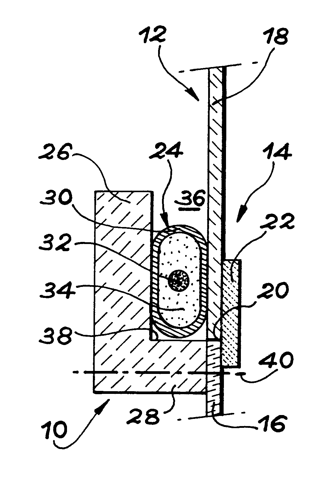
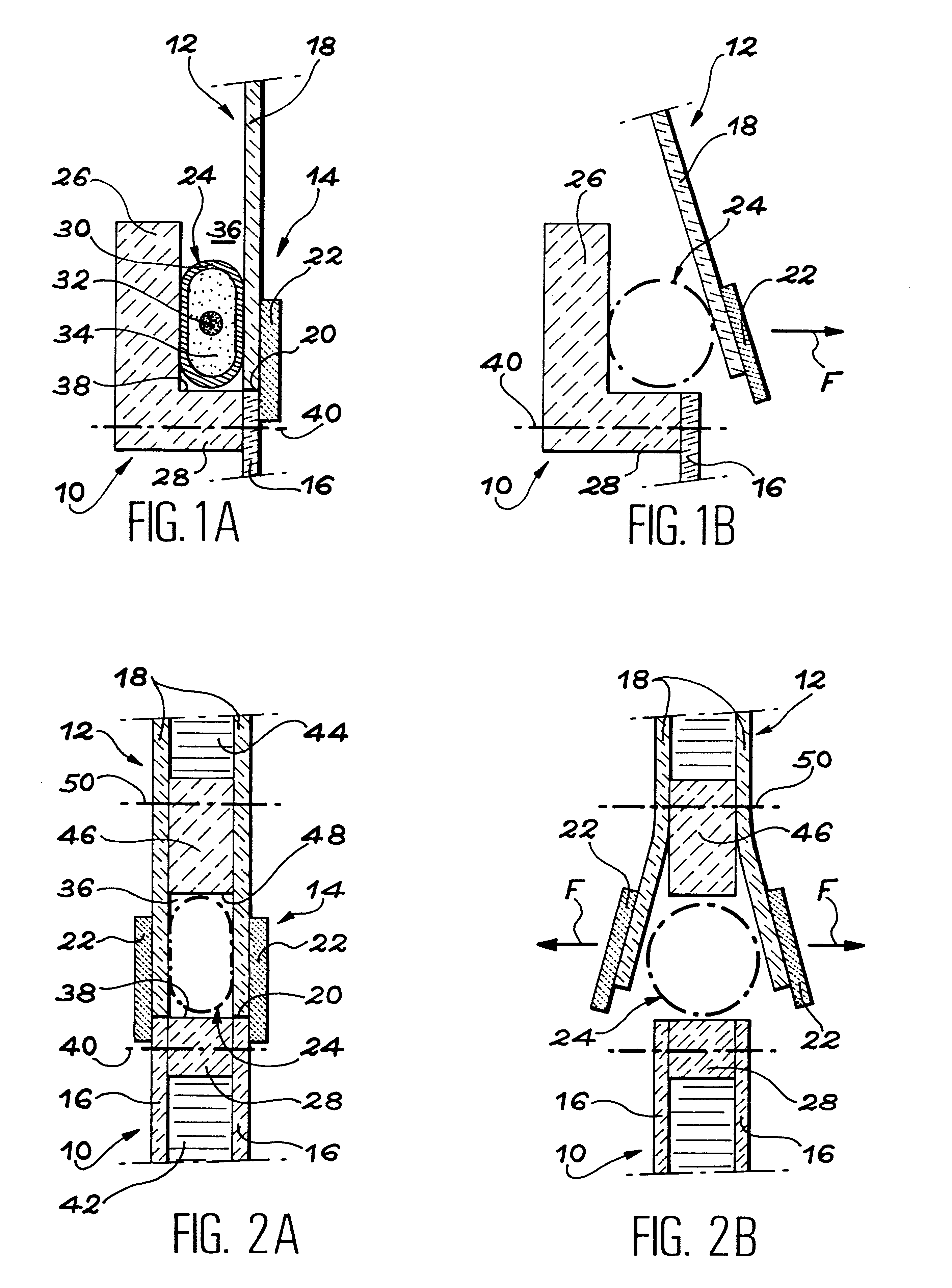
In this first embodiment, the first and second structural assemblies 10, 12 respectively comprise a first nonmetallic part 16 and a second nonmetallic part 18.

The nonmetallic material from which are formed the parts 16 and 18 can be of different types without passing beyond the scope of the invention. A preferred application relates to the case where said material is a composite material, formed from sheets of long fibres embedded in a resin matrix. As is well known in the art, such parts can be obtained by covering sheets of fibres impregnated with thermosetting resin, followed by the polymerization of the resin.

In addition, the parts 16 and 18 can have various shapes without passing outside the scope of the invention. In the case illustrated in FIG. 1A, the parts 16 and 18 are in the form of plates, having substantially uniform and equal thicknesses. These plates can be planar, inwardly curved, or have any other shape adapted to the envisaged application.

In the embodiment illustra...

second embodiment

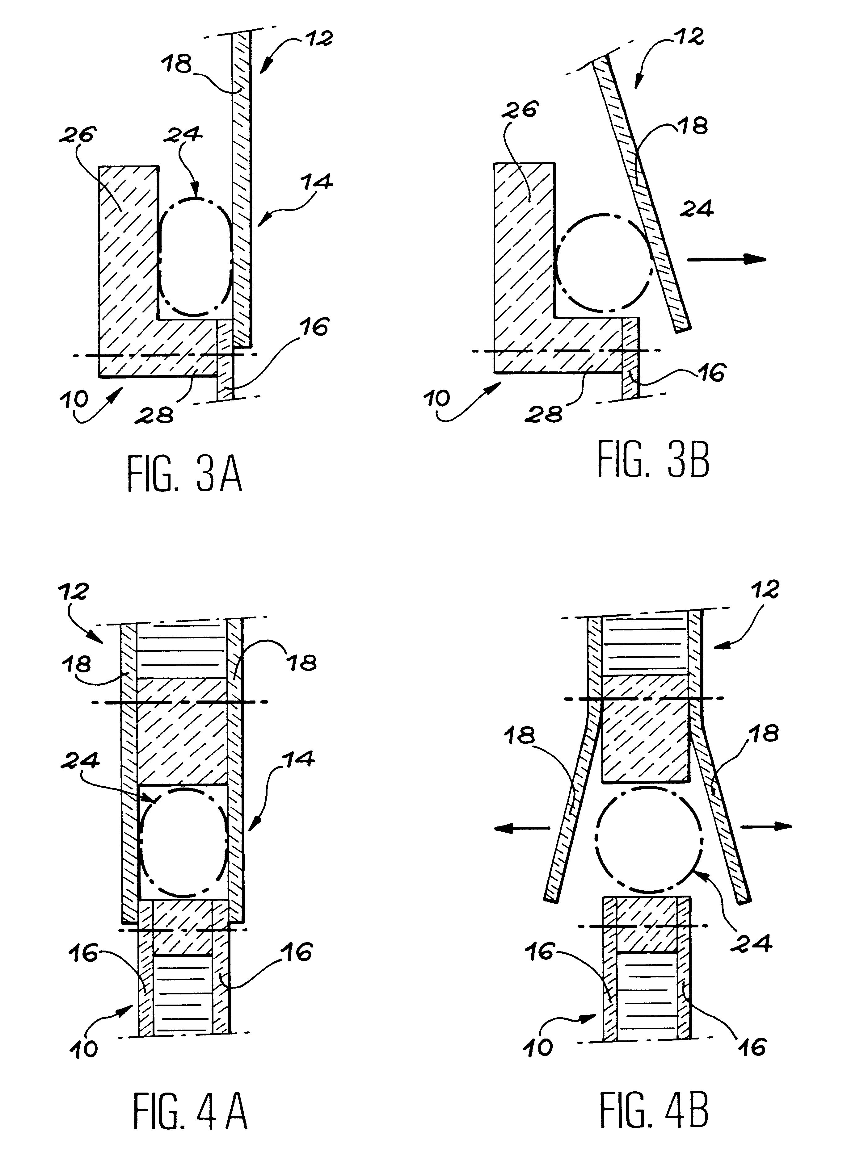
FIGS. 3A and 3B diagrammatically show device 14 according to the invention. As in FIGS. 1A and 1B, FIGS. 3A and 3B relate to the separation of two single parts 16, 18 belonging to two separate assemblies 10, 12, which are initially linked and which it is wished to separate. Therefore the general arrangement is comparable to that described hereinbefore relative to FIGS. 1A and 1B, so that a new and detailed description will not be given.

The embodiment of FIGS. 3A and 3B differs from the first embodiment by the nature of the linking means by which assemblies 10 and 12 are fixed to one another, prior to the operation of the pyrotechnic expansion tube 24.

In the case of FIGS. 3A and 3B, the linking part 22 is eliminated and the link between the parts 16, 18 is ensured by the direct bonding of an end portion of the second part 18 to an end portion of the first part 16, facing the spacer 28. Consequently the parts 16 and 18 are not placed end to end or edge to edge, but instead overlap on ...


PUM


Abstract

A provisional linking and pyrotechnic separation device is placed between two assemblies made from nonmetallic materials such as composite materials. Prior to separation, parts belonging to each of the two assemblies are fixed to one another, either by direct bonding of the parts to one another, or by bonding a linking part to the parts. The device includes a pyrotechnic expansion tube acting directly on one of the parts to be separated. A precise, clean and well localized separation of the assemblies consequently takes place during the use or operation of the pyrotechnic expansion tube.

Description

The invention relates to a device using a pyrotechnic expansion tube for separating two initially interconnected assemblies.Such a device can in particular be used in the aeronautical and space industries for provisionally linking two structural assemblies and for controlling their separation in a very short time.PRIOR ARTWhen two initially interconnected metallic assemblies have to be irreversibly separated in a short time and by remote control, use is currently made of pyrotechnic cutting devices integrated into the junction zone between the two assemblies.When it is wished to carry out a clean cutting, i.e. with a minimum amount of dust being released, use is generally made of a cutting device including a pyrotechnic expansion tube.The express "pyrotechnic expansion tube" designates a tight, deformable, metal tube, in which runs a detonating cord or fuse. A flexible material, such as silicone rubber, is interposed between the detonating fuse and the envelope. Prior to firing, the...

Claims


Application Information

Patent Timeline
Patent Type & Authority Patents(United States)
IPC IPC(8): F15B15/00F15B15/19F42B15/38F42B15/00
CPCF15B15/19F42B15/38
Inventor SALORT, CEDRIC
Owner SOC NATIONALE INDUSTRIELLE AEROSPATIALE SA
Learn More