Pump systems and methods

a pump system and pump technology, applied in the direction of positive displacement liquid engine, sealing/packing, borehole/well accessories, etc., can solve the problems of sand still being a major problem and the difficulty of pumping, and achieve the effect of increasing the pressure in the pump annulus, increasing pump efficiency, and inhibiting sand production

Inactive Publication Date: 2001-06-26
MUTH PUMP
View PDF12 Cites 83 Cited by
  • Summary
  • Abstract
  • Description
  • Claims
  • Application Information

AI Technical Summary

Benefits of technology

A principal object of the present invention is to provide a pumping system having parallel power tubing and production tubing strings in which production is flowed up the production tubing through a flow control valve connected at the lower end of the pumping system. A rod operated insertable and removable pump plunger is disconnectably connected into the power tubing wherein the pump plunger may be removed from and inserted into the power tubing without the need to remove the tubing string from the well. A hollow pull tube is ...

Problems solved by technology

Often heavy viscous oils such as produced from California formations which are relatively close to the earth's surface contain sand and are difficult to pu...

Method used


Image

  • Pump systems and methods
  • Pump systems and methods
  • Pump systems and methods

Examples


Embodiment Construction

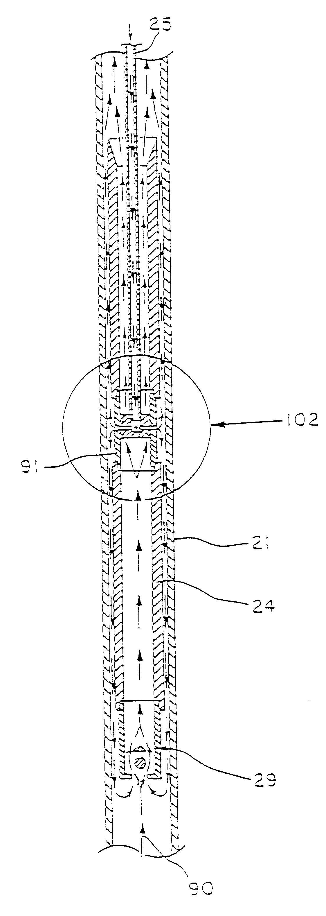
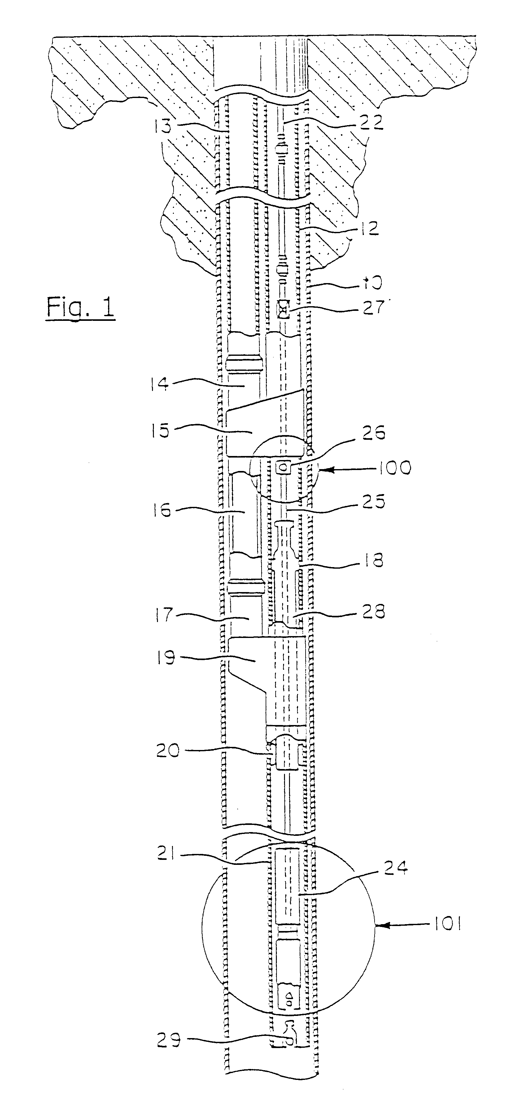
FIG. 1 shows an overall sectional view of a pumping assembly in accordance with the present invention. A casing 10 is operably positioned in the well. Parallel power tubing 12 and production tubing 13 strings are positioned in the casing and connect with the bottom hole assembly which houses a down hole tubing pump and insert plunger 24 having lubricating ports 81-84 (see FIGS. 4-5). The power tubing 12 and the production tubing 13 provide paths between the surface and a position in a well where well fluids are produced. As shown in FIG. 1, parallel anchor 15 has a first passage on the left and a second passage on the right of the anchor. A stab in tubing member 14 forming the bottom of the tubing string 13 extends through the first passage and is attached to the top of a connecting pup tubing 16 that screws into the top of a standing valve nipple 17. A crossover flow head 19 attaches to the bottom of the standing valve nipple 17 on the left side. The right side of the crossover flo...


PUM


Abstract

A pumping system comprises a pump barrel that is adapted to be placed into a well casing. A plunger is reciprocatably positioned within the pump barrel and has an open top end, a bottom end, and a traveling valve at the bottom end. A connector is coupled to the plunger below the top end. A rod is coupled to the connector and is translatable to reciprocate the plunger within the pump barrel using an upstroke and a downstroke. Further, the top end of the plunger is adapted to direct particulate into the plunger and away from the pump barrel upon each upstroke.

Description

1. Field of the InventionThe present invention is directed to a pumping system for producing well fluids from petroleum producing formations penetrated by a well. Once aspect of the present invention includes the use of dual parallel tubing strings having the lower portions connected by a crossover flow connection, one of the tubing strings, i.e., the production tubing string, forming a flow path for flowing production fluids to the surface and the other, i.e., the power tubing string, for providing a conduit for inserting, operating and removing a rod-activated pump plunger used to lift well fluids from the well and to move the well fluids up the well to the surface through the crossover flow connection. A flow control valve for controlling production flow is also provided. A lubricating plunger is provided to direct fluid from the annulus between the power tubing and the rods to an area between the barrel of the pump and the lubricating plunger to increase the efficiency of the pu...

Claims


Application Information

Patent Timeline
IPC IPC(8): E21B33/122E21B34/00E21B34/06E21B33/12E21B43/12F04B53/10F04B53/18F04B53/22F04B47/02F04B53/00F04B53/12F04B47/00
CPCE21B33/122E21B34/06E21B43/121E21B43/126E21B43/127F04B47/02F04B53/125F04B53/18F04B53/22
Inventor MUTH, GAROLD M.
Owner MUTH PUMP
Why Eureka
Try Eureka