Detachable handle for vessels

a technology for detachable handles and vessels, which is applied in the direction of containers preventing decay, sealing, transportation and packaging, etc., can solve the problems of difficult and expensive, difficult and expensive, and the attachment mechanism of detachable handles is rather complicated, so as to achieve easy and inexpensive manufacturing, simple structure, and easy to fabricate

Inactive Publication Date: 2001-06-26
INNOVATION IP HLDG
View PDF14 Cites 63 Cited by
  • Summary
  • Abstract
  • Description
  • Claims
  • Application Information

AI Technical Summary

Benefits of technology

A button connected to the cam latch, by a post, is utilized to draw the cam latch rearward against the biasing force of the spring. The spring is positioned in a cavity formed between a cover plate and base plate of the latching assembly. The post extends through aligned slots in the cover plate and the base plate and through the cavity with the button extending above the cover plate and the cam latch extending below the base plate. One end of the spring abuts against an end of the handle grip and the opposite end of the spring abuts against the post to which the cam latch is secured. The spring thereby biases the cam latch forward away from the end of the handle grip.
The invention provides a vessel with a detachable handle that (a) is simple in structure and relatively easy and inexpensive to make, because it has only a few parts that are easy to fabricate; (b) is easy to engage with the vessel and quickly and automatically locks in place via the latching mechanism, without the need to without manipulate of levers or tabs; (c) does not require precise engagement or manipulation in order to achieve a secure engagement or lock with the vessel, because the user need only insert the foot of the mounting plate engaging tip into the slot in the mounting plate on the vessel and allow the handle to rotate downward; (d) allows the user to see or visualize whether the a proper engagement or lock has been achieved when the handle is attached to the vessel; (e) provides positive visual feedback of engagement and locking as noted immediately above, and also provides auditory confirmation of engagement and locking when the latch snaps forward under the mounting plate; and (f) eliminates or substantially reduces the movement or "play" of the handle when it is attached and locked in place, as is more fully described below. The invention has other advantages as will be noted from the drawings and detailed description, and the statement above is not intended to be limiting.

Problems solved by technology

Most detachable handles have rather complicated attachment mechanisms, require similarly complicated matching mounts on the utensils, and are difficult and expensive to make.
Many of the attachment means also block the user's view of the locking mechanism so that one cannot see if the proper engagement or lock has been achieved.
Still other detachable handles are difficult to detach or remove from the utensil, making their use less appealing and, as a practical matter, making it difficult, if not impossible, to switch handles on utensils while they contain and / or are being used to cook food.
Most also do not provide positive feedback, such as a sound or other visual signal, that the handle is securely locked in place.
Many such attachment mechanisms also allow some movement or "play" in the handle once it is attached, making the attachment somewhat unstable or loose when attached to the utensil.

Method used


Image

  • Detachable handle for vessels
  • Detachable handle for vessels
  • Detachable handle for vessels

Examples


Embodiment Construction

The following convention is used in this detailed description. The words "upper," "top," "above," and words of like import refer to that direction in the properly oriented, upright drawings. The words "down," bottom," "lower," "below," and words of like import refer to that direction in the properly oriented, upright drawings. The words "front," "forward," and words of like import refer to the left hand direction in the properly oriented, upright drawings, and the words "rear," "rearward," and "back" refer to the right hand direction in the properly oriented, upright drawings.

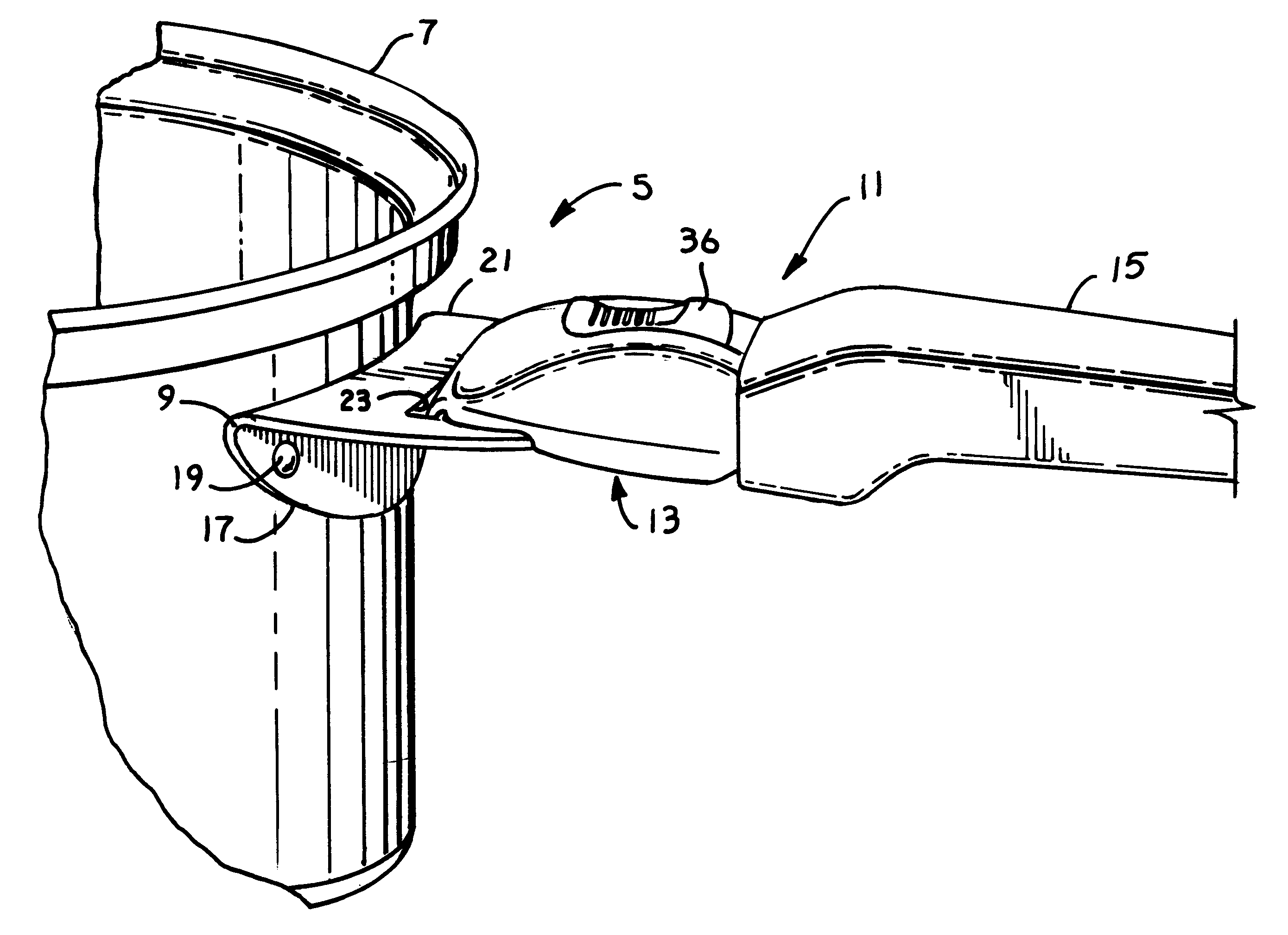
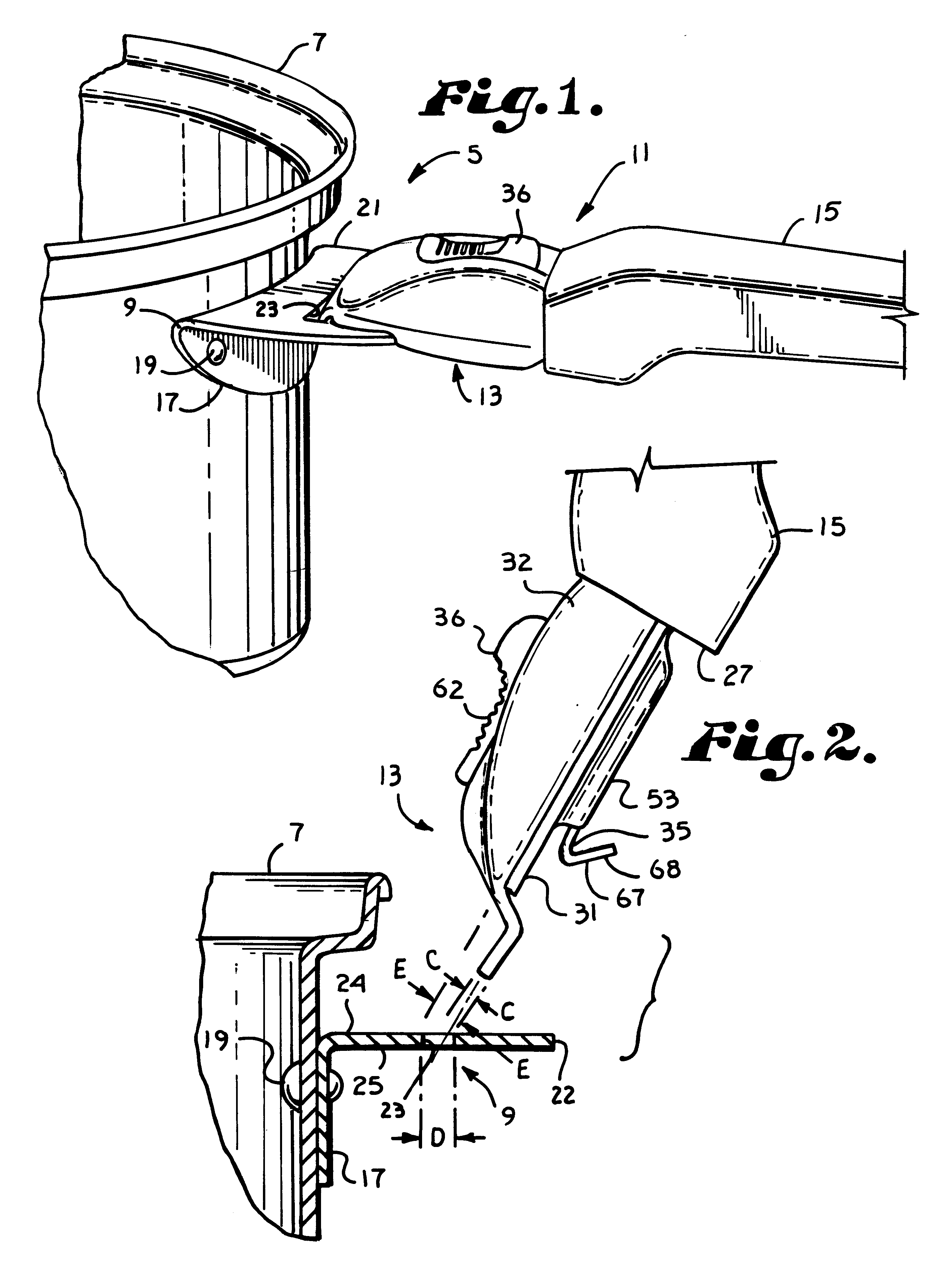
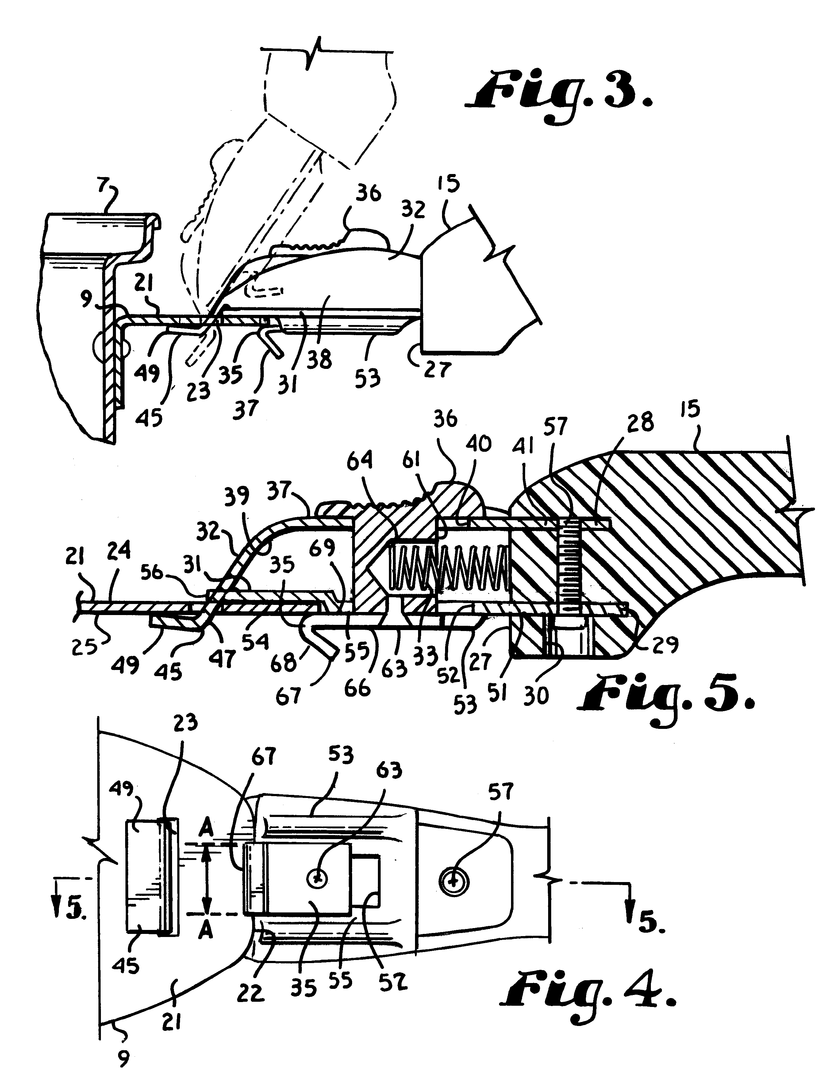
Referring to the drawings in more detail, the reference numeral 5 refers to a detachable handle mount assembly of the present invention shown secured to a vessel 7. The vessel 7 may be a pot, pan, or other common container or utensil used to hold or cook food or other substances. The handle mount assembly 5 comprises a mount 9 attached to the vessel 7 and a handle assembly 11. The handle assembly 11 comprises a...


PUM


Abstract

A detachable handle assembly for a vessel includes a slotted mounting plate connected to the vessel and a handle grip with a latching assembly connected at one end. The latching assembly releasably engages the slotted mounting plate to connect the handle grip to the vessel. The latching assembly includes a base plate and a cover with an engagement tip formed at a forward end thereof and a spring biased cam latch slidably mounted in spaced relation below a lower surface of the base plate. The engagement tip includes a leg extending below the base plate of the latching assembly and a foot extending forward from the leg. The latching assembly is connected to the mounting plate by holding the handle grip at an angle relative to the mounting plate and inserting the engagement tip foot into a slot in the mounting plate. The handle grip is then pivoted downward until the cam latch engages a distal end of the mounting plate, causing the spring biased cam latch to move rearward around the distal end of the mounting plate and then back forward beneath the mounting plate, securing the mounting plate between the cam latch and the base plate of the latching assembly.

Description

This invention is related to detachable handles for pots, pans, and other vessels or utensils.BACKGROUND OF INVENTIONVessels with detachable handles are advantageous for a variety of reasons. Detachable handles allow users to use one handle on several vessels, are easy and efficient to store, eliminate wasted storage space by making it unnecessary to provide space to accommodate the projection of the handle, and allow for easier stacking of pots and pans. The detachable handles themselves are, of course, easy and convenient to store.A variety of vessels with detachable handles are shown in the prior art. Most detachable handles have rather complicated attachment mechanisms, require similarly complicated matching mounts on the utensils, and are difficult and expensive to make. Many detachable handles require mechanical manipulation of levers or tabs and / or rather precise engagement or manipulation to assure a tight, locked engagement with the utensil. Many of the attachment means als...

Claims


Application Information

Patent Timeline
Patent Type & Authority Patents(United States)
IPC IPC(8): A47J45/00A47J45/07
CPCA47J45/071
Inventor KWAN, PARK SOON
Owner INNOVATION IP HLDG
Why Eureka
Try Eureka