Method of manufacturing polarizing plate

a technology of polarizing glass and manufacturing method, which is applied in the field of polarizing glass, can solve the problems of difficult to supply a large area of polarizing glass, difficult to equalize the size of silver halide particles during heating and stretching glass, and complicated process

Inactive Publication Date: 2001-06-26
TDK CORPARATION
View PDF9 Cites 77 Cited by
  • Summary
  • Abstract
  • Description
  • Claims
  • Application Information

AI Technical Summary

Problems solved by technology

Further, each process is remarkably complicated.
Moreover, it is considered difficult to equalize the size of the silver halide particles during heating and stretching the glass.
Therefore, in view of the manufacturing processes, it is extremely difficult to supply a polarizing glass having a large area.
However, it is extremely difficult to form the metallic thin films uniformly on the respective walls by means of oblique deposition.
If unevenness occurs in thickness of the metallic thin films, the grid line widths and the grid pitches do not become uniform so that a polarizing property is adversely affected.
For forming a pattern of a large area, a concavoconvex pattern forming operation using the EB drawing apparatus takes much time.

Method used


Image

  • Method of manufacturing polarizing plate
  • Method of manufacturing polarizing plate
  • Method of manufacturing polarizing plate

Examples


Embodiment Construction

Now, concrete examples will be shown to explain the present invention in further detail. Preparation of Polarizing Plate Sample

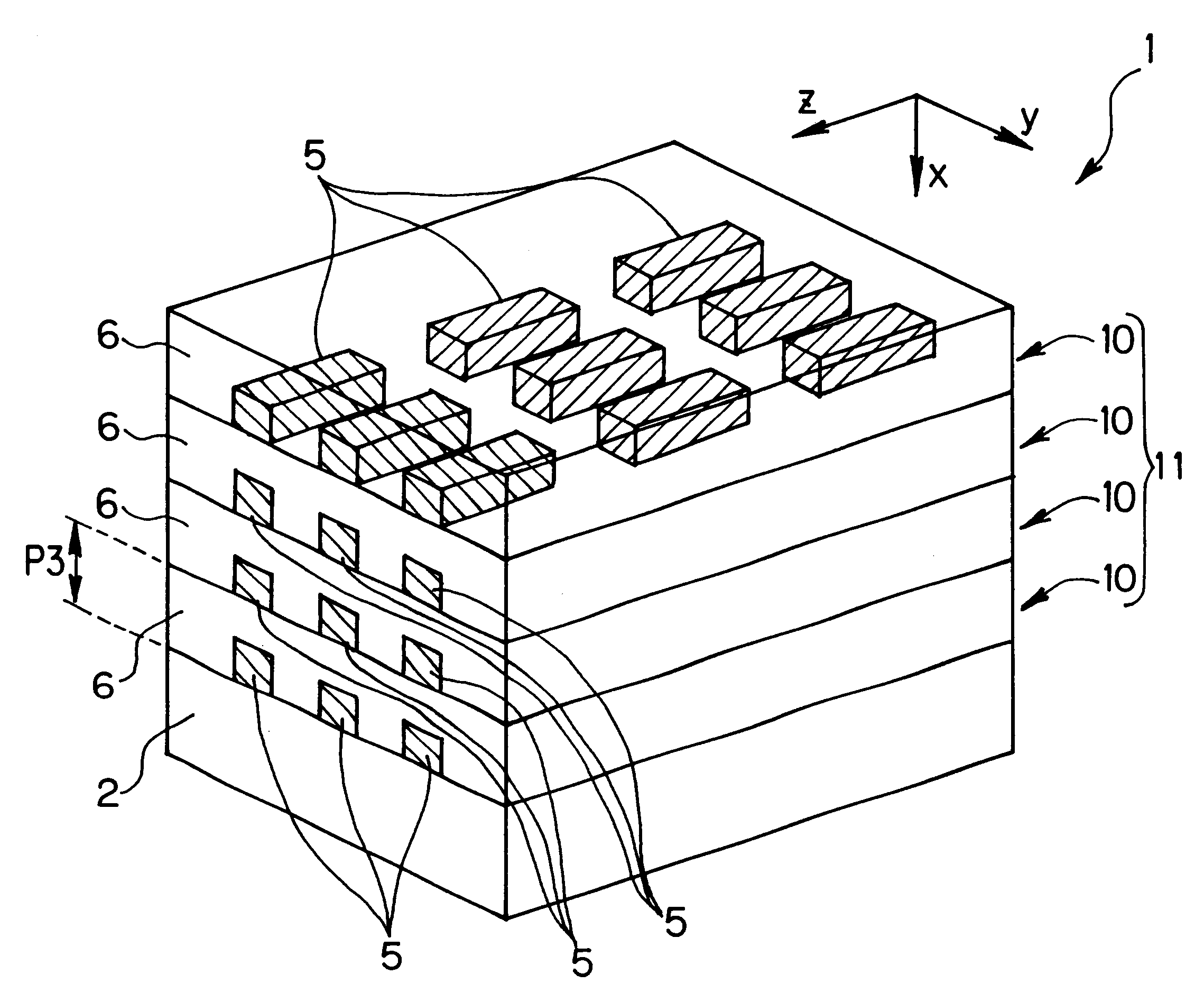
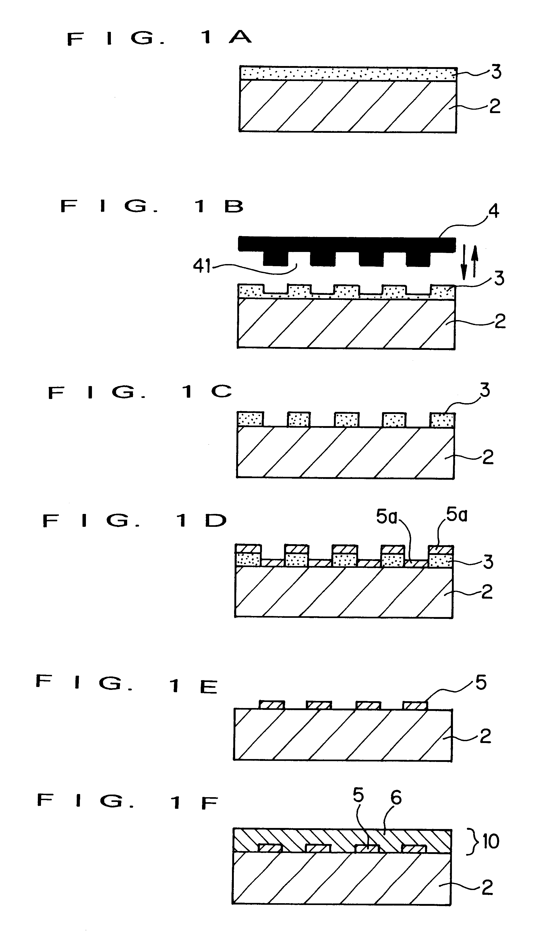
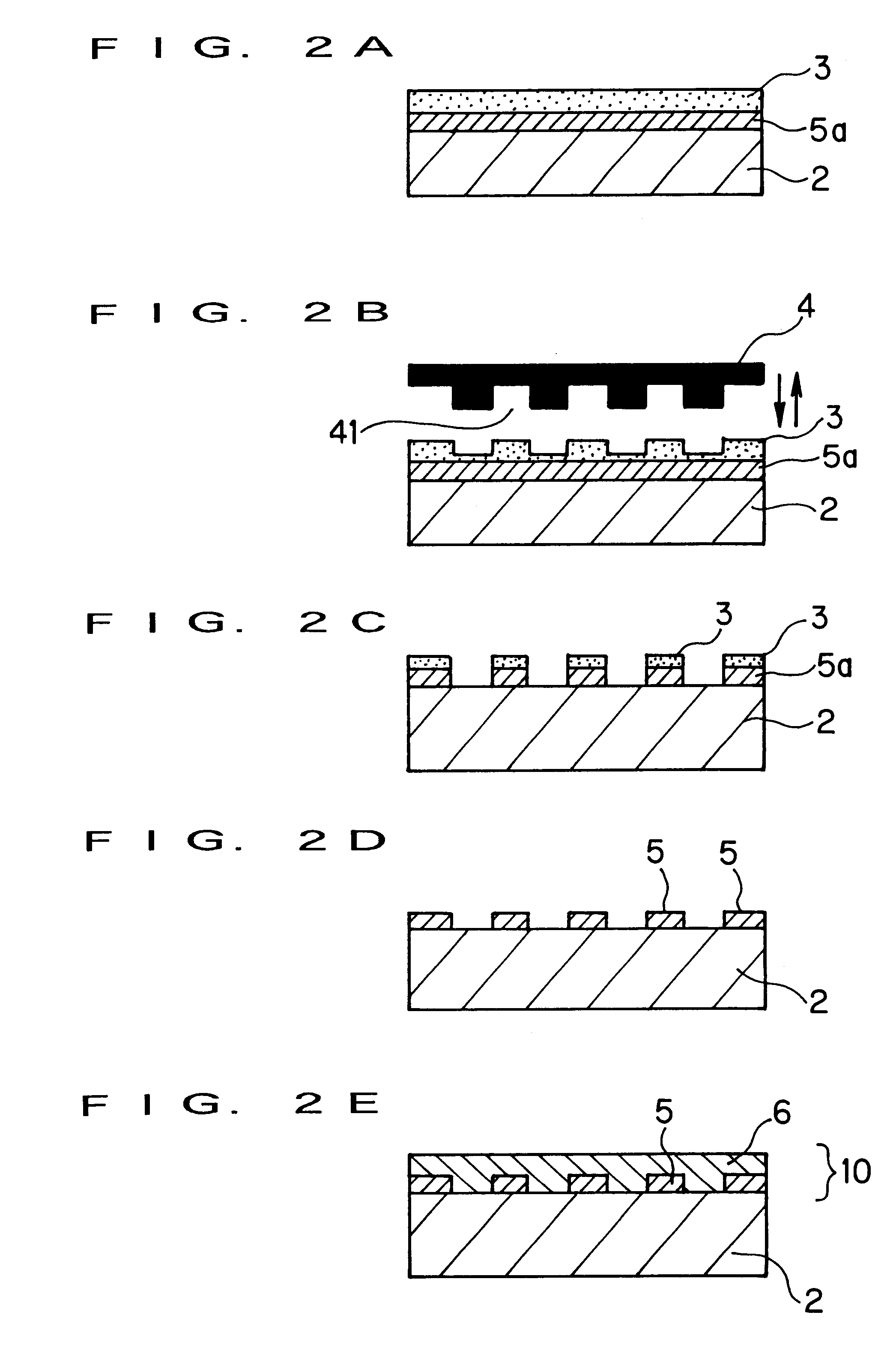
In this example, a polarizing plate was produced according to the processes shown in FIG. 1. A forming die 4 was made of silicon dioxide (SiO2) as a base material, and a concavoconvex pattern as shown in FIG. 4 was formed on the surface of the forming die 4 using an electron beam drawing method. In FIG. 4, (A) is a plan view of the forming die 4 and (B) is a front view of the forming die 4.

In FIG. 4, dimensions of each of convex portions 4a of the forming die 4 were such that L1=300 nm, L2=25 nm and D (height) =80 nm, and further, P1=P2=1000 nm. The size of the whole forming die 4 was set to 2cm .times.2cm. Accordingly, the number of the convex portions 4a shown in FIG. 4 is only for convenience of explanation and differs from the actual number thereof.

Using the foregoing forming die 4, the polarizing plate was produced in the following manner:

First, a resin...


PUM

PropertyMeasurementUnit
axis lengthaaaaaaaaaa
thicknessaaaaaaaaaa
aspect ratiosaaaaaaaaaa

Abstract

A method of manufacturing a polarizing plate of a resonance absorption effect type wherein plural bar-like polarizing members are arranged in a light-transmittable polarizing matrix layer with major axes thereof orienting in a constant direction. The method includes a preparing process of a forming die for preparing a forming die having a concavoconvex pattern corresponding to a layout pattern of the bar-like polarizing members, a forming process of a concavoconvex pattern on a resin layer for forming a resin layer directly or indirectly on a substrate and pressing the forming die onto the resin layer so as to form a concavoconvex pattern on the resin layer, a forming process of bar-like polarizing members for forming the bar-like polarizing members in the foregoing layout pattern using the concavoconvex pattern of the resin layer, and a forming process of a polarizing matrix layer for forming the light-transmittable polarizing matrix layer so as to bury the formed bar-like polarizing members. Accordingly, the polarizing plate of the resonance absorption effect type can be obtained, which is low in price, massproducible, high in extinction ratio, high in performance and high in reliability.

Description

1. Field of the InventionThe present invention relates to a polarizing plate for use in optical communication, optical recording, sensor or the like and, in particular, to a polarizing plate of a resonance absorption effect type which generates the optical anisotropy by dispersing and arranging metal like islands in a dielectric substance or on the surface of the dielectric substance and which is highly reliable and massproducible at a low price in view of manufacturing processes.2. Description of the Prior ArtAs a linear polarizing plate heretofore used in a liquid crystal display or the like, a linear polarizing film using iodine or dye with a resin film as a base is well known. In the film, by stretching the base film, dichroic materials of iodine or dye are oriented to obtain a polarizing property.JP-A-56-169140 proposes a method of manufacturing a polarizing plate, wherein a metallic compound, such as silver halide, is dispersed into glass which is then heated and stretched so ...

Claims


Application Information

Patent Timeline
Patent Type & Authority Patents(United States)
IPC IPC(8): G02B5/20G02B5/18G02B5/30B29D11/00B29K105/22C23C14/04
CPCG02B5/1809G02B5/204G02B5/3058
Inventor KOMURO, EIJUKINERI, TOHRU
Owner TDK CORPARATION
Why Eureka
Try Eureka