Stone and tile table saw apparatus

a table saw and tile technology, applied in the field of saws, can solve the problems of obstructing workpiece size and movement, inefficient and awkward use, and water retaining walls around the periphery of the table element,

Inactive Publication Date: 2001-07-03
BENSON WALTER J
View PDF14 Cites 47 Cited by
  • Summary
  • Abstract
  • Description
  • Claims
  • Application Information

AI Technical Summary

Problems solved by technology

Many have been inefficient and awkward to use.
A problem with Williams is that water retaining walls around the periphery of the table element limit and obstruct work piece size and movement.
Another problem with Williams is that the cooling water does not reach the central area of the blade, so that cooling is incomplete and blade warping may result.
Moreover, water scattered on the table element must flow back to the center of the element to drain, limiting drainage efficiency.
Still further problems with Williams are that debris inside the saw guard cannot be readily viewed to alert the user to the need for cleaning, and the saw guard itself can obstruct work piece movement.
A problem with Toru Naito, et al. is that the water delivered to the blade only strikes one blade face, so that cooling is incomplete and imbalanced, and the delivery tube also obstructs user access to the blade.
Another problem with Toru Naito, et al. is that the casing obstructs work piece movement during cutting and limits the size of the work piece.
A problem with Smith is that the work platform is too small to receive and maneuver large work pieces.
Another problem is that the Smith saw guard does not support itself in a raised position, so that cutting thick work pieces is awkward.
A problem with Wain is that there is no convenient way to position and hold a work piece, which must be engaged above the shroud.
Wain also apparently fails to provide means for preventing the cooling oil from splashing on and otherwise accumulating on the drive belt and drive motor.
A problem with Crocetti is that the enclosure and the saw guard both substantially obstruct movement and positioning of a work piece, such as during cutting of a U-shaped bottom connection.
Both also limit the size of the work piece Crocetti can accept.
The sides of the vice and the box limit the size of the work piece Bein can accept, and completely inhibit movement of the piece necessary to making many types of cuts.

Method used


Image

  • Stone and tile table saw apparatus
  • Stone and tile table saw apparatus
  • Stone and tile table saw apparatus

Examples


Embodiment Construction

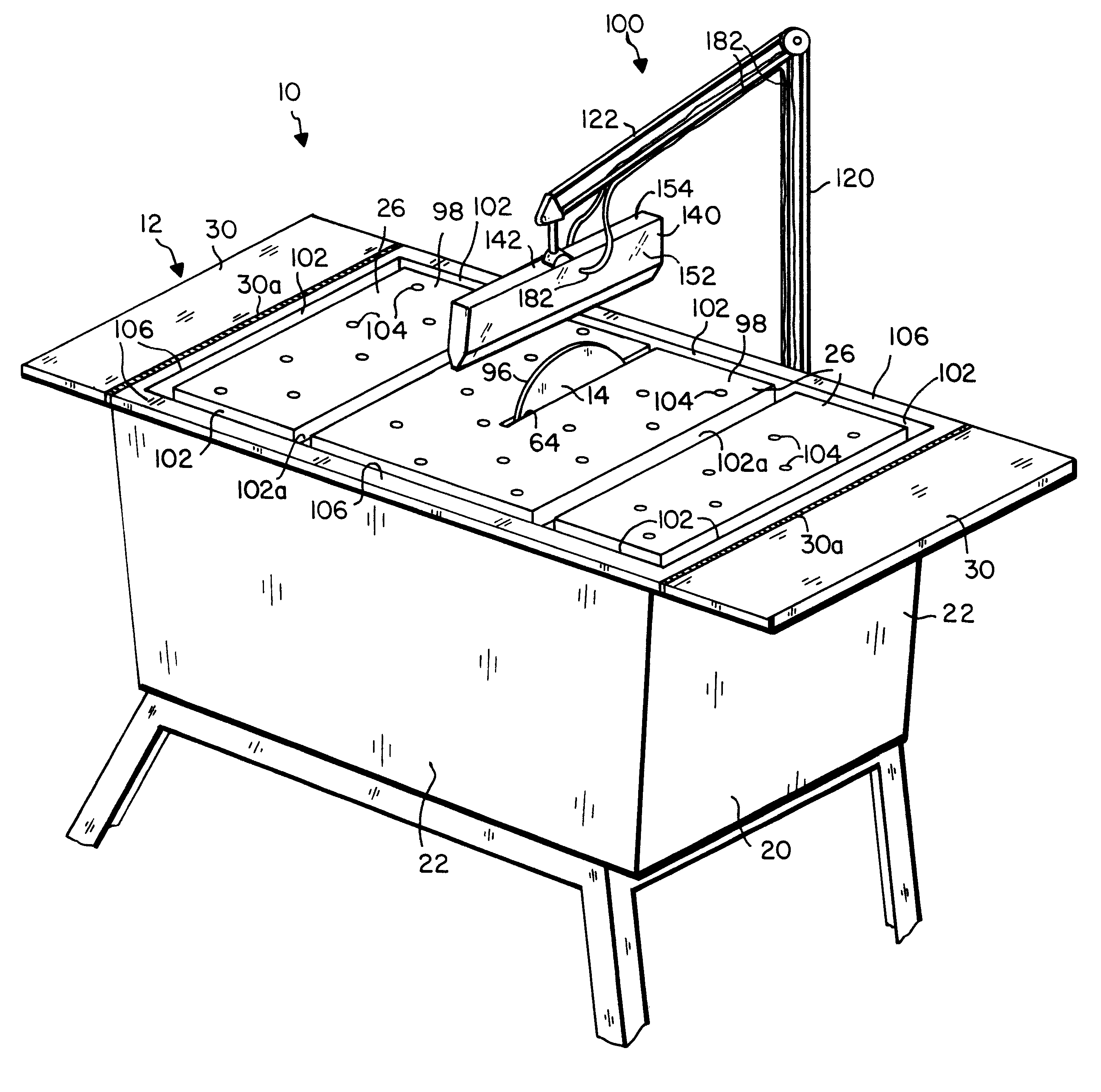
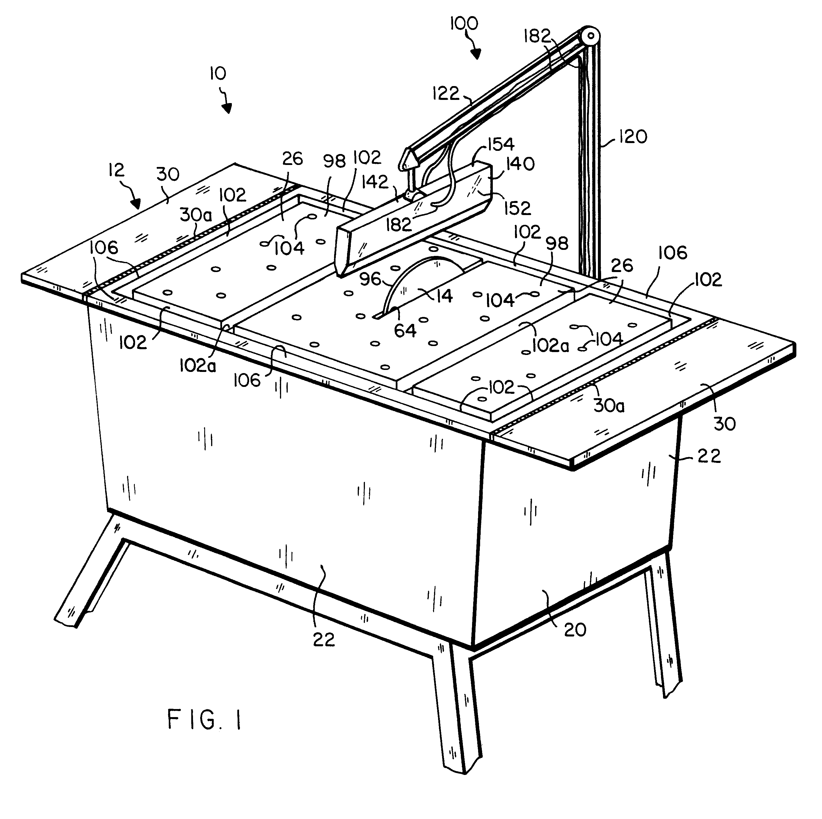
Referring to FIGS. 1-8, a stone and tile saw apparatus 10 is disclosed. Apparatus 10 includes a saw table 12, a saw blade 14, a blade drive motor 16, a blade cooling system, a saw guard 140, and a guard mounting arm assembly 100.

Saw Table

Saw table 12 includes a housing 20 with four housing side walls 22, a housing bottom wall 24 joined in sealing relationship with three side walls 22, and a table top wall 26 secured to a side wall 22 with hinges 32, such that top wall 26 rests on side walls 22. Top wall 26 preferably rests on an elongate water-tight seal 28 provided along the upper surfaces of side walls 22. See FIGS. 1 and 5. Top wall 26 preferably includes lateral leaf portions 30 mounted with hinges 30a which are recessed flush into the top surfaces of top wall 26 and leaf portions 30 adjacent to the lateral edges of top wall 26. Leaf portions 30 fold outwardly, and the hinged ends of leaf portions 30 act as stops to hold extended leaf portions 30 horizontal. Leaf portions 30 mee...


PUM

PropertyMeasurementUnit
elevationsaaaaaaaaaa
transparentaaaaaaaaaa
frictionaaaaaaaaaa

Abstract

A saw apparatus for cutting a work piece includes a circular saw blade, a saw blade drive mechanism including a motor drivably connected to the saw blade and having a motor pulley, and including a blade mounting structure, a saw table including a housing with a housing side wall, and a housing top wall having a blade passing opening and being hingedly secured to and resting on the housing side wall, a housing partition defining a drive mechanism chamber and a blade mounting chamber within the housing having a drive mechanism chamber bottom wall sealingly joined to the housing side wall, and a cooling liquid contained within the blade mounting chamber, so that the blade mounting mechanism includes a blade axle extending through the housing partition between the blade mounting chamber and the drive mechanism chamber, and the blade protrudes up through the blade passing opening and down into the cooling liquid, and a blade axle pulley is secured to the blade axle, passes through the housing partition, and a belt extends from the blade axle pulley to the motor pulley.

Description

1. Field of the InventionThe present invention relates generally to the field of saws for cutting stone and tile work pieces. More specifically, the present invention relates to a stone and tile saw apparatus including a circular blade, a drive motor, a saw table, a blade cooling system, a saw guard and a laterally spaced guard arm mounting assembly. The saw table has a horizontal top wall with a drive assembly housing mounted underneath including housing side walls. The table top wall is hingedly secured to and rests on the side walls.The housing is divided by intersecting and unified motor and pulley partitions forming a combined housing partition into a blade mounting chamber and a combined blade motor and pulley chamber. The housing bottom wall extends beneath and seals the lower end of the blade mounting chamber. The motor and pulley chamber is open at the bottom for ventilation and easy access for servicing. The drive assembly includes a blade mounting bearing-loaded mandrel s...

Claims


Application Information

Patent Timeline
Patent Type & Authority Patents(United States)
IPC IPC(8): B23D47/02B23D59/02B23D59/00B23D47/00B28D1/04B28D1/02
CPCB23D47/025B28D1/04B23D59/02B25H1/02
Inventor BENSON, WALTER J.
Owner BENSON WALTER J
Why Eureka
Try Eureka