Hydraulic stent deployment system

a technology of stent and stent body, which is applied in the field of medical devices, can solve the problems of difficult, if not impossible, to retrieve the stent or reposition the stent, and little control over the exact placement of the sten

Inactive Publication Date: 2001-07-03
CODMAN & SHURTLEFF INC
View PDF40 Cites 228 Cited by
  • Summary
  • Abstract
  • Description
  • Claims
  • Application Information

AI Technical Summary

Problems solved by technology

With these placements systems there is very little control over the exact placement of the stent since the stent may be ejected to a position some distance beyond the end of the cann

Method used


Image

  • Hydraulic stent deployment system
  • Hydraulic stent deployment system
  • Hydraulic stent deployment system

Examples


Embodiment Construction

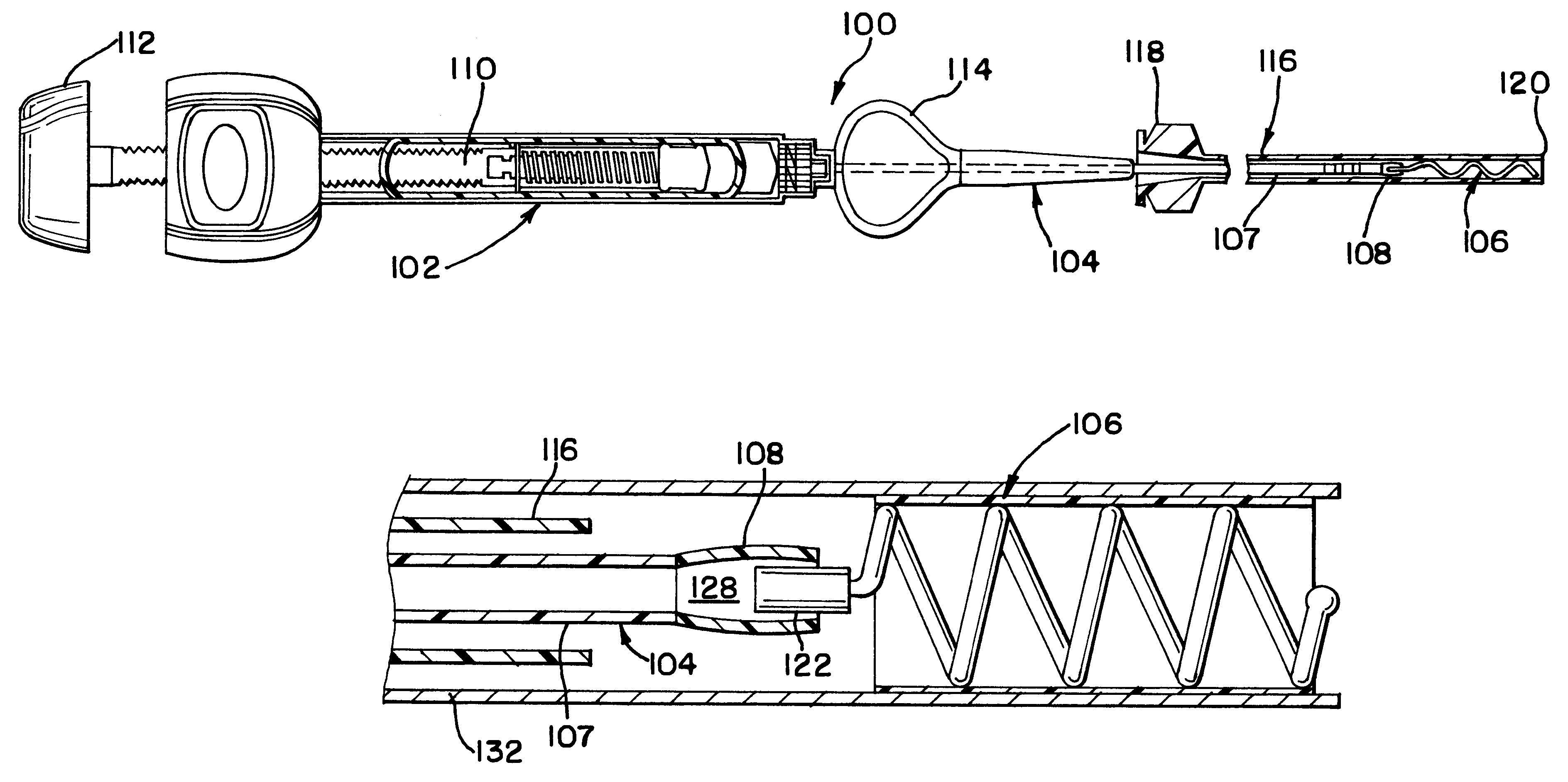
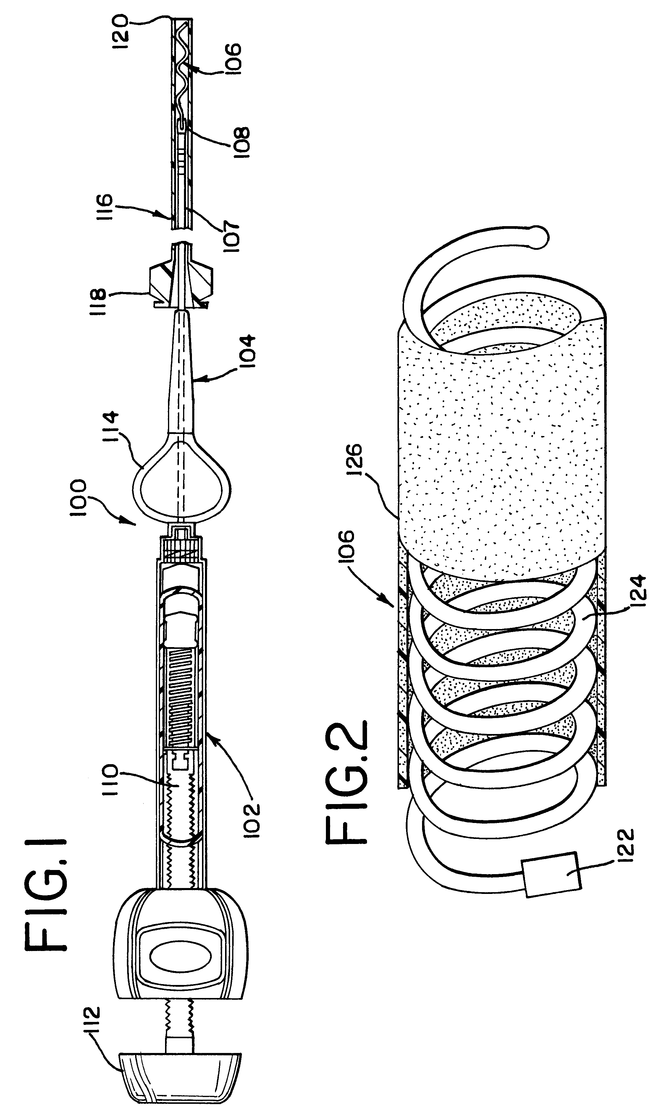
FIG. 1 generally illustrates the intravascular stent deployment system 100 which is comprised of a hydraulic injector or syringe 102, coupled to the proximal end of a catheter 104. A stent 106 is disposed within the lumen of the distal section 108 of the catheter 104. The proximal end of the stent 106 is tightly held within the lumen of the distal section 108 of the catheter 104 until the deployment system is activated for release of the stent. As may be seen, the syringe 102 includes a threaded piston 110 which is controlled by a handle 112 for infusing fluid into the interior of the catheter 104. Also as illustrated, the catheter 104 includes a winged hub 114 which aids in the insertion of the catheter into the access catheter 116 which has a proximal hub 118 that is placed in the vascular system of the body.

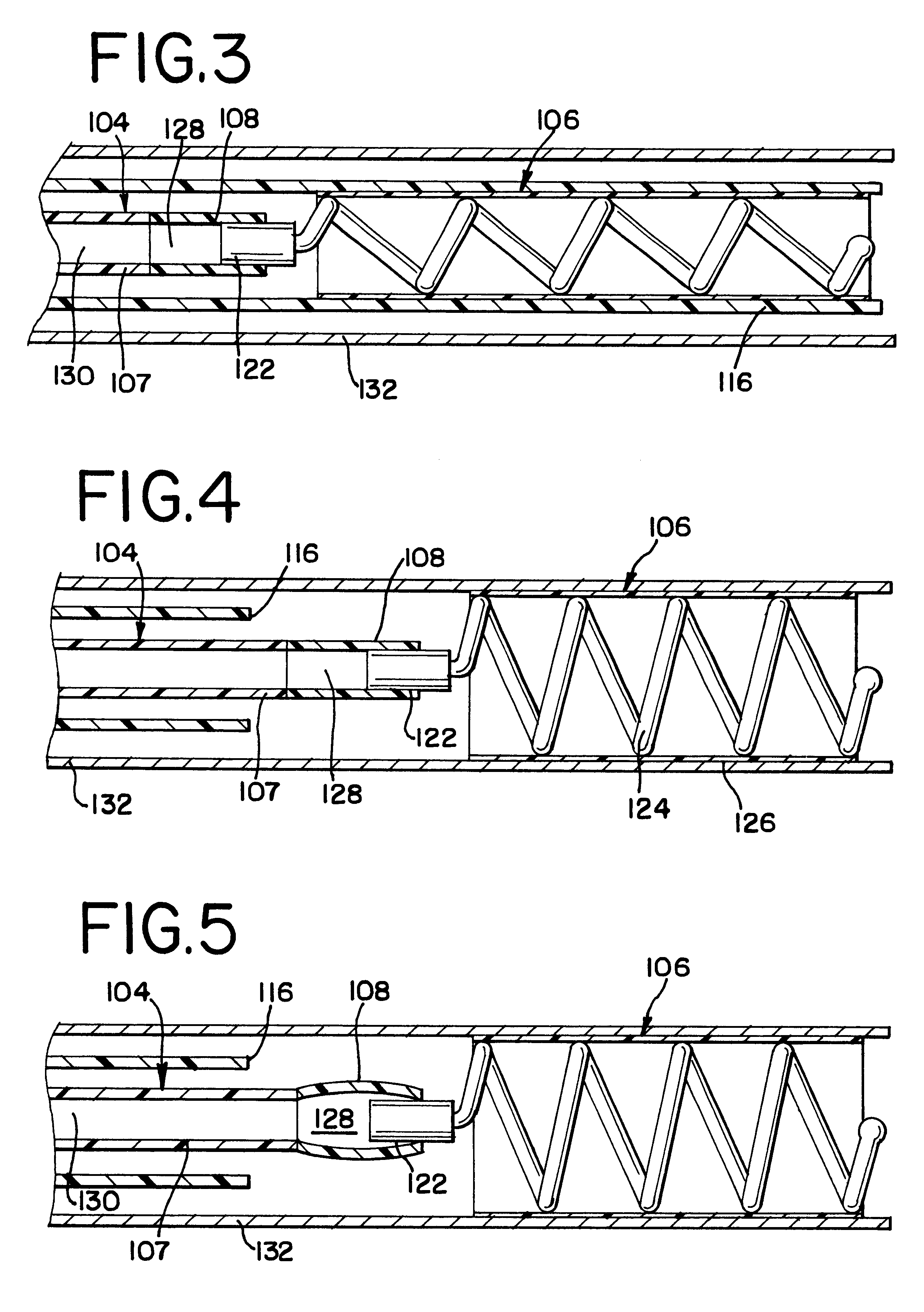
FIG. 2 illustrates in more detail an alternate embodiment of the stent 106. The stent 106 is comprised of a headpiece element 122 attached to a coil 124 and a cover 126 which ...


PUM


Abstract

The present invention relates to a medical device for placing an intravascular stent at a preselected location within a vessel of the human body, and more particularly, relates to a catheter having a distal tip for retaining the stent in order to transport the stent to a preselected position within the vessel and a control mechanism for releasing the stent at the preselected position.

Description

1. Field of the InventionThe present invention relates to a medical device for placing an intravascular stent at a preselected location within a vessel of the human body, and more particularly, relates to a catheter having a distal tip for retaining the stent in order to transport the stent to a preselected position within the vessel and a control mechanism for releasing the stent at the preselected position.2. Description of the Prior ArtFor many years flexible catheters have been used to place various devices within the vessels of the human body. Such devices include dilatation balloons, radiopaque fluids, liquid medications and various types of occlusion devices such as balloons and embolic coils. Examples of such catheter devices are disclosed in U.S. Pat. No. 5,108,407, entitled, "A Method And Apparatus For Placement Of An Embolic Coil"; U.S. Pat. No. 5,122,136, entitled, "Endovascular Electrolytically Detachable Guidewire Tip For The Electroformation Of Thrombus In Arteries, V...

Claims


Application Information

Patent Timeline
IPC IPC(8): A61F11/00A61M29/00A61F2/06A61F2/82A61F2/84A61F2/88A61M25/12
CPCA61F2/88A61F2/966A61F2/95
Inventor HIESHIMA, GRANT
Owner CODMAN & SHURTLEFF INC
Why Eureka
Try Eureka