Method of manufacture of high Young's modulus thermoelastic inkjet printer

a thermoelastic and inkjet printing technology, applied in the field of inkjet printing, can solve the problems of limiting the amount of mass production throughput given any particular capital investment, difficult production of ink jet printheads, and adding a substantial manufacturing expens

Inactive Publication Date: 2001-07-03
SILVERBROOK RES PTY LTD +1
View PDF7 Cites 123 Cited by
  • Summary
  • Abstract
  • Description
  • Claims
  • Application Information

AI Technical Summary

Problems solved by technology

Unfortunately, in mass production techniques, the production of ink jet printheads is quite difficult.
The separate material processing steps required in handling such precision devices often adds a substantially expense in manufacturing.
Additionally, side shooting ink jet technologies (U.S. Pat. No.

Method used


Image

  • Method of manufacture of high Young's modulus thermoelastic inkjet printer
  • Method of manufacture of high Young's modulus thermoelastic inkjet printer
  • Method of manufacture of high Young's modulus thermoelastic inkjet printer

Examples


Embodiment Construction

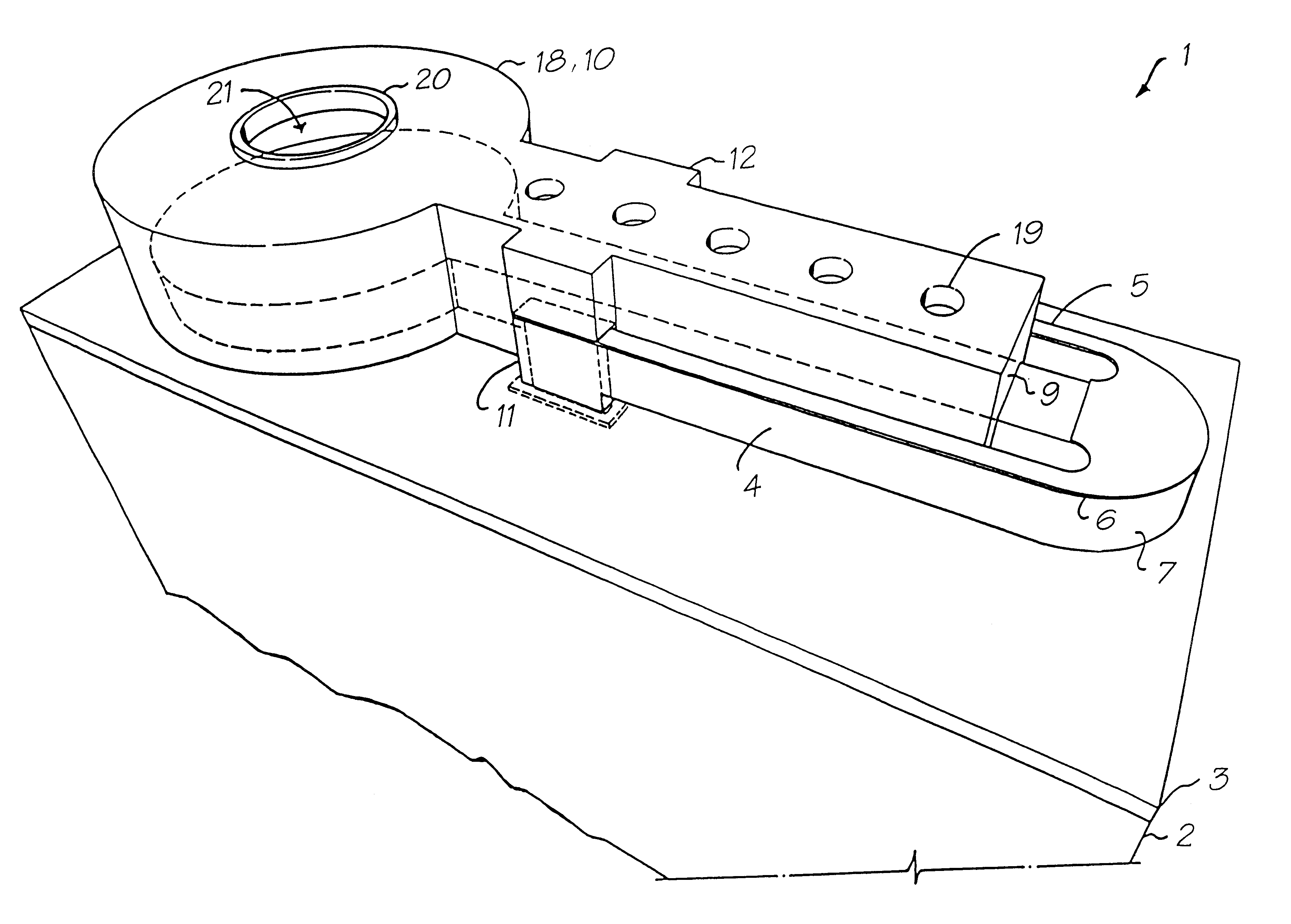
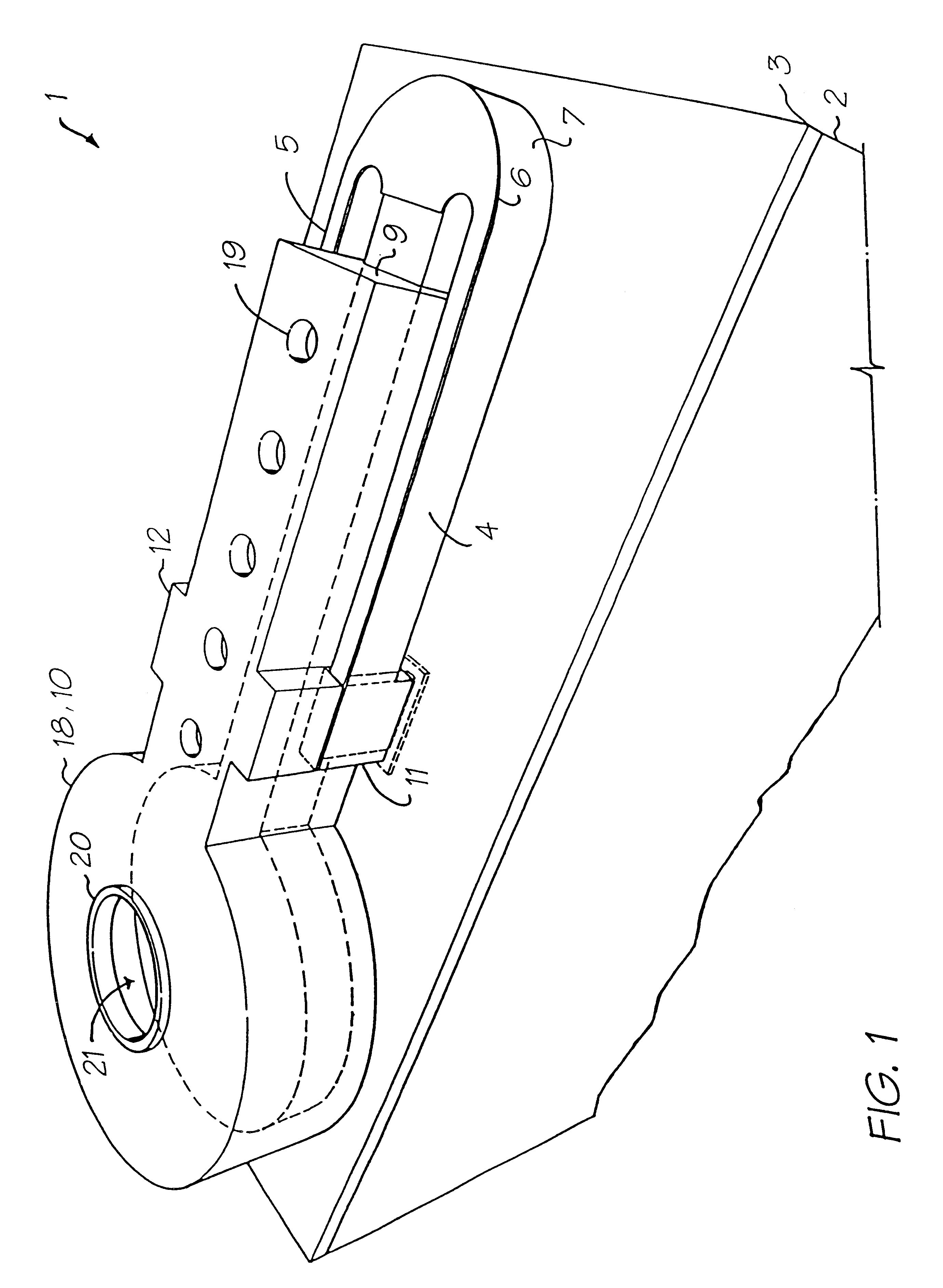
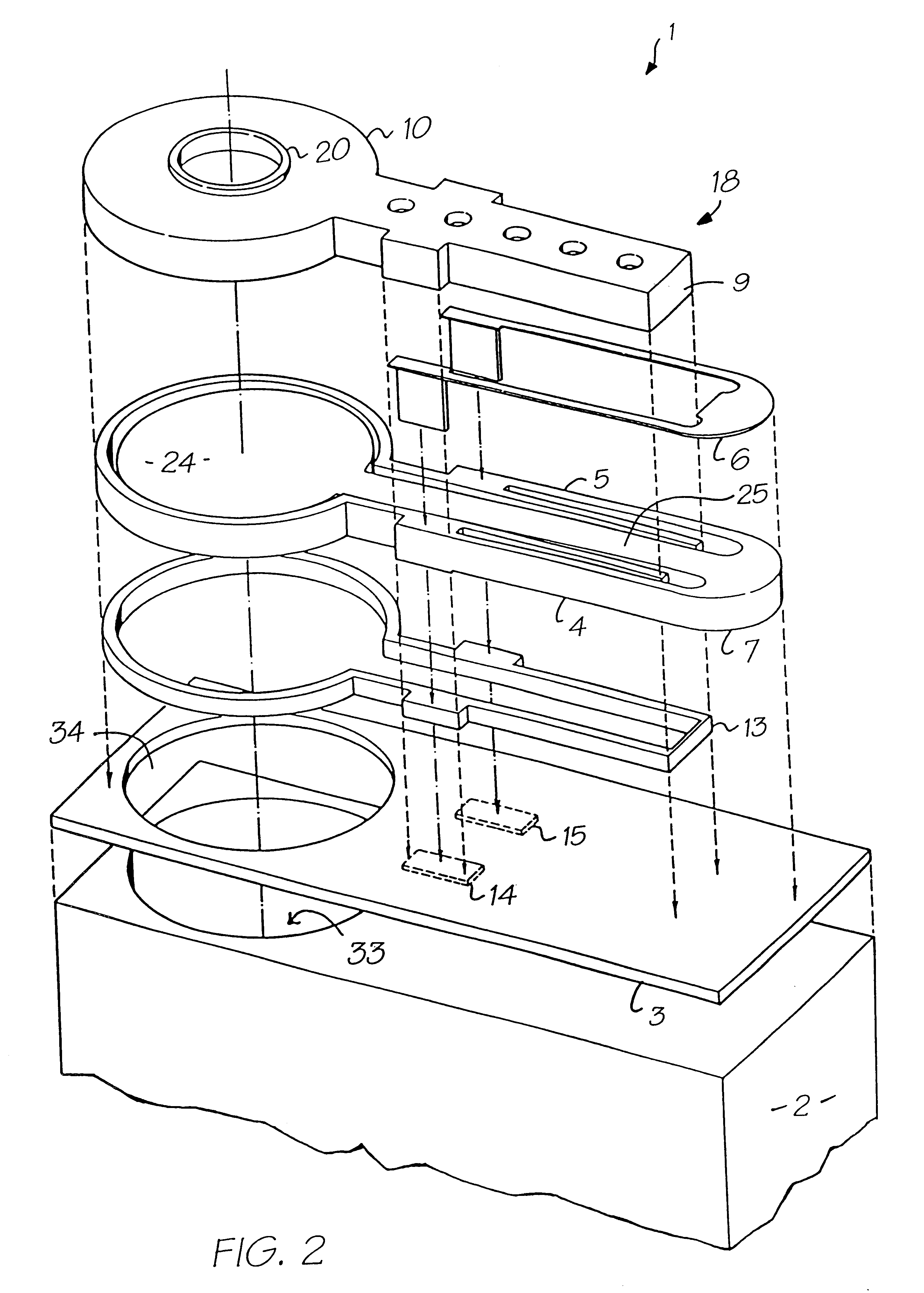
In the preferred embodiment, the actuation of an actuator for the ejection of ink is based around the utilisation of material having a High Young's modulus.

In the preferred embodiment, materials are utilised for the ejection of ink which have a high bend efficiency when thermally heated. The inkjet print head is constructed utilising standard MEMS technology and therefore should utilise materials that are common in the construction of semi-conductor wafers. In the preferred embodiment, the materials have been chosen through the utilisation of a bend efficiency for actuator devices which can be calculated in accordance with the following formula. ##EQU1##

Of course, different equations could be utilised and, in particular, the factors on the numerator and the denominator have been chosen for their following qualities.

Coefficient of thermal expansion: The greater the coefficient of thermal expansion, the greater will be the degree of movement for any particular heating of a thermal act...


PUM


Abstract

A method of manufacturing a thermally actuated ink jet printhead includes the step of initially providing a wafer having a circuitry layer including the electrical circuitry necessary for the operation of a thermal actuator. A first sacrificial layer is deposited on the wafer and is etched. A Young's modulus layer is deposited to form a first layer of a thermal actuator and a portion of a nozzle chamber wall. A conductive heater material layer is provided and has a portion interconnected to the circuitry layer. A second sacrificial layer is deposited and etched in preparation for nozzle chamber walls. A nozzle wall material layer is deposited to form the walls of the nozzle chamber. The nozzle wall material layer is etched to define a nozzle port for the ejection of ink. The sacrificial layers are etched away to release the thermal actuator. The nozzle chamber walls are formed to define a fulcrum for the thermal actuator.

Description

The following Australian provisional patent applications are hereby incorporated by cross-reference. For the purposes of location and identification, U.S. patent applications identified by their U.S. patent application serial numbers (USSN) are listed alongside the Australian applications from which the U.S. patent applications claim the right of priority.Not applicable1. Field of the InventionThe present invention relates to the field of inkjet printing and, in particular, discloses a method of manufacturing an ink jet printhead.2. Background of the InventionMany ink jet printing mechanisms are known. Unfortunately, in mass production techniques, the production of ink jet printheads is quite difficult. For example, often, the orifice or nozzle plate is constructed separately from the ink supply and ink ejection mechanism and bonded to the mechanism at a later stage (Hewlett-Packard Journal, Vol. 36 no 5, pp33-37 (1985)). The separate material processing steps required in handling s...

Claims


Application Information

Patent Timeline
IPC IPC(8): B41J11/70B41J2/14B41J15/04B42D15/10B41J2/16B41J2/175B41J3/42B41J11/00G06F1/16G06K1/12G07F7/12G06K1/00G06K19/073G06K19/06G06K7/14G11C11/56G07F7/08H04N1/32H04N5/262H04N5/225H04N1/21B41J2/165H04N1/00B41J3/44
CPCB41J2/14427H04N5/2628B41J2/1629B41J2/1631B41J2/1632B41J2/1635B41J2/1639B41J2/1642B41J2/1643B41J2/1645B41J2/1646B41J2/1648B41J2/17596B41J3/445B41J11/0005B41J11/70B41J15/04B82Y30/00G06K1/121G06K7/14G06K7/1417G06K19/06037G11C11/56H04N5/225B41J2/1628B41J2/16585B41J2002/041B41J2002/14346H04N23/00
Inventor SILVERBROOK, KIA
Owner SILVERBROOK RES PTY LTD
Why Eureka
Try Eureka