Mobile radio communication system with macro and micro cell handoff based on mobile determined crossing rates and fading rates

a radio communication system and micro cell technology, applied in the field of mobile radio communication system, can solve the problems of deteriorating process performance on the radio base station side, each mobile station not having sufficient information about the system structure and current system state, and each mobile station failing to select an optimal channel

Inactive Publication Date: 2001-07-03
NEC CORP
View PDF10 Cites 102 Cited by
  • Summary
  • Abstract
  • Description
  • Claims
  • Application Information

AI Technical Summary

Problems solved by technology

However, in this method, since each mobile station only measures the field intensities of available channels and selects a channel with the strongest field intensity, the mobile station does not sufficiently have information about the system structure and the current system state.
Thus, each mobile station occasionally fails to select an optimum channel.
As a first problem in such a conventional mobile radio communication system, when communications between mobile stations and a relevant radio base station get congested or when a new channel is assigned between each mobile station and the relevant radio base station or the current channel is switched to a new channel, the process performance on

Method used


Image

  • Mobile radio communication system with macro and micro cell handoff based on mobile determined crossing rates and fading rates
  • Mobile radio communication system with macro and micro cell handoff based on mobile determined crossing rates and fading rates
  • Mobile radio communication system with macro and micro cell handoff based on mobile determined crossing rates and fading rates

Examples


Embodiment Construction

A mobile radio communication system according to an embodiment of the present invention will be described with reference to the accompanying drawings.

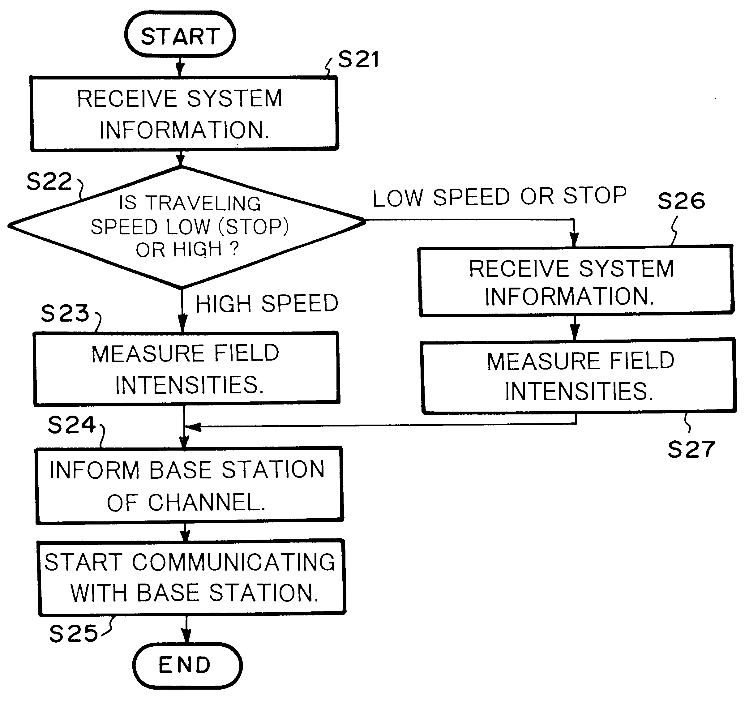
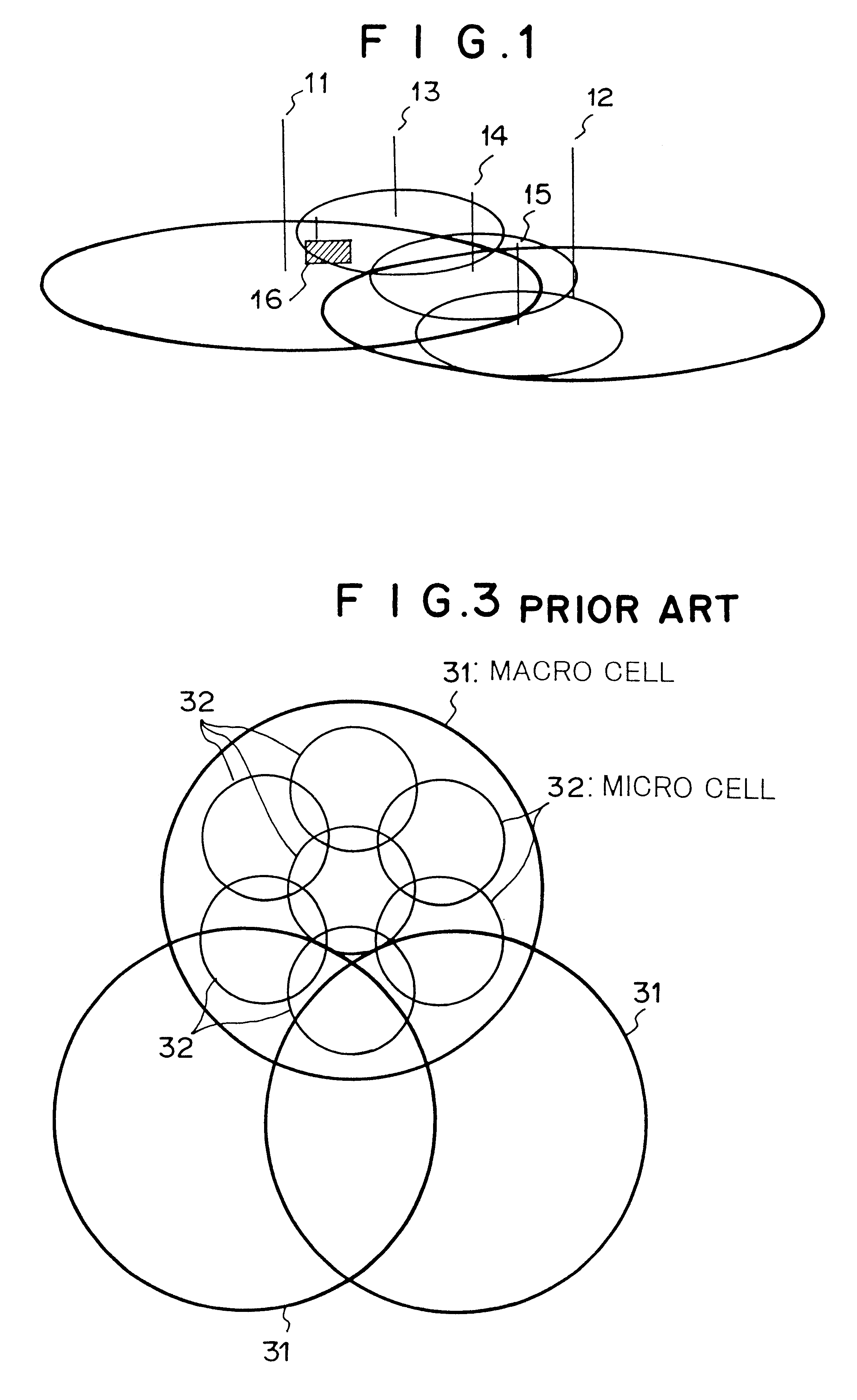
The mobile radio communication system according to the present invention comprises a plurality of mobile stations, a plurality of radio base stations, and a radio-base-station controlling station. The radio base stations provide service areas for the mobile stations. The radio-base-station controlling station controls the radio base stations. The radio base stations are categorized as macro cell radio base stations and micro cell radio base stations. The macro cell radio base stations form macro cells (wide radio areas). The micro cell radio base stations form micro cells (narrow radio areas) that are smaller than the macro cells. It is preferable that the macro cells and the micro cells independently cover the entire service area (namely, the macro cells and the micro cells overlap with each other).

For simplicity, in the following des...


PUM


Abstract

A radio base station broadcasts system information through a control channel. Each mobile station receives system information (at step S21) and determines the moving speed thereof (at step S22). When the mobile station is moving at high speed, the mobile station measures the field intensities of available channels on which the mobile station can communicate with a macro cell radio base station (at step S23 or S27). When the mobile station is moving at low speed, the mobile station measures the field intensities of available channels on which the mobile station can communicate with a micro cell radio base station (at step S27 or S23). However, when the radio base station to which the mobile station is moving is different from the radio base station from which the mobile station has received the control channel at first, the mobile station receives new system information from the relevant base station at step S26. The mobile station selects a channel corresponding to the measured result and starts communicating with the new radio base station (at steps S24 and S25).

Description

1. Field of the InventionThe present invention relates to a mobile radio communication system of which a service area is composed of macro cells that are subdivided into micro cells.2. Description of the Related ArtAs a conventional mobile radio communication system, a related art reference disclosed in Japanese Patent Laid-Open Publication No. 5-130018 is known. In the mobile radio communication system, to solve problems of shortage of channels and reduction of occurrences of hand-off, as shown in FIG. 3, the service area is composed of macro cells 31, each of which is composed of micro cells 32. A terminal unit communicates with a macro cell radio base station or a micro cell radio base station corresponding to the traveling speed of the terminal unit.In the mobile radio communication system, to allow a mobile station in the service area to communicate with a radio base station, a communication channel should be assigned for each communication session demanded for communication. N...

Claims


Application Information

Patent Timeline
IPC IPC(8): H04Q7/38H04W36/04
CPCH04W36/04
Inventor YAMASHITA, TETSUYA
Owner NEC CORP
Why Eureka
Try Eureka