Stun gun

a technology of shock weapons and immobilizers, applied in the field of shock guns, can solve the problems of ineffectiveness of shock weapons in controlling suspects an astounding 63% of the time, insufficient probe spacing of manual connection shock weapons, and sustained involuntary contraction of targets, so as to increase the discharge gap.

Inactive Publication Date: 2001-07-10
RESNICK BARNET
View PDF6 Cites 59 Cited by
  • Summary
  • Abstract
  • Description
  • Claims
  • Application Information

AI Technical Summary

Benefits of technology

It is therefore a principal object of the present invention to provide an improved hand-held electrical stun gun having a wider discharge gap for increasing effectiveness.
It is still another object of the present invention to provide a stun gun configuration wherein the shape of the end of the gun which contacts a target, promotes more effective muscle reaction to the ensuing electrical discharge.

Problems solved by technology

Police Department, the weapons were found to be ineffective at helping to control suspects an astounding 63% of the time.
Experiments reported in U.S. Pat. No. 5,841,622 establish that the typical probe spacing on the manually connected shock weapons is inadequate for immobilizing a human target.
At least several additional inches of space is needed between the contacts or the weapon shock may be insufficient to cause a sustained involuntary contraction of the target's muscle, which contraction is sufficient to rigidly fixate joints and hamper ambulation.
Moreover, experimental observations also disclosed in U.S. Pat. No. 5,841,622 establish that at safe power levels of 5 watts or less, even with adequate spacing between the contacts, the shocks are insufficient to cause muscular contractions that will move limbs.
This, in turn, increases the likelihood of a sustained involuntary flexing or extending contraction of the muscle.
Stun guns with ballistic delivery systems do not have this capacity as the ammunition detonating and target disabling circuitry is usually inaccessible absent the addition of circuitry.

Method used


Image

  • Stun gun
  • Stun gun
  • Stun gun

Examples


Embodiment Construction

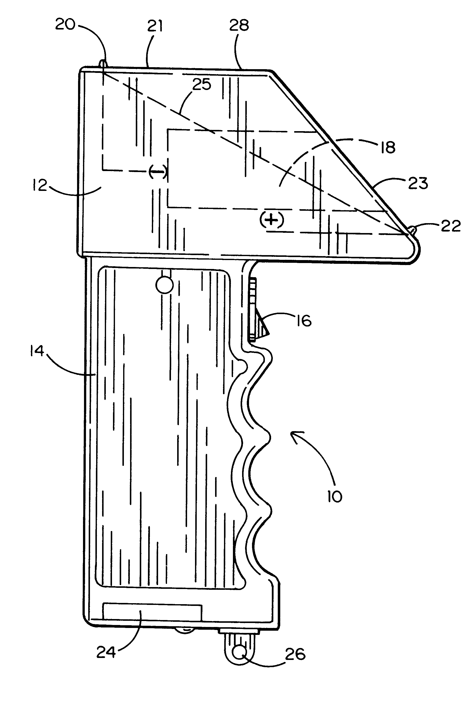
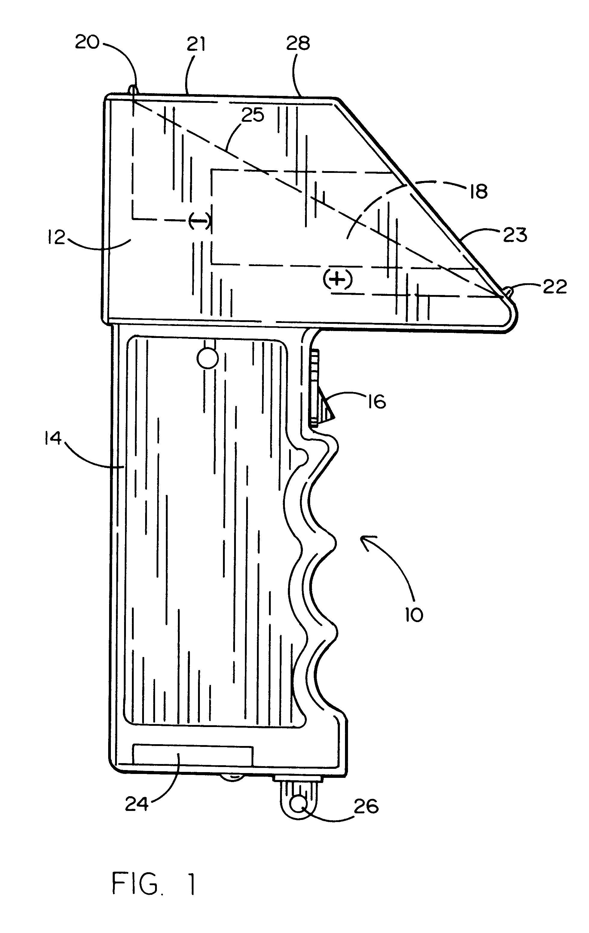
Referring to the accompanying figures, it will be seen that a stun gun 10 in accordance with the present invention comprises a head portion 12 and an integral handle portion 14. The stun gun electronics (not shown) are conventional and are contained within handle portion 14 where they may be selectively activated by a trigger switch 16.

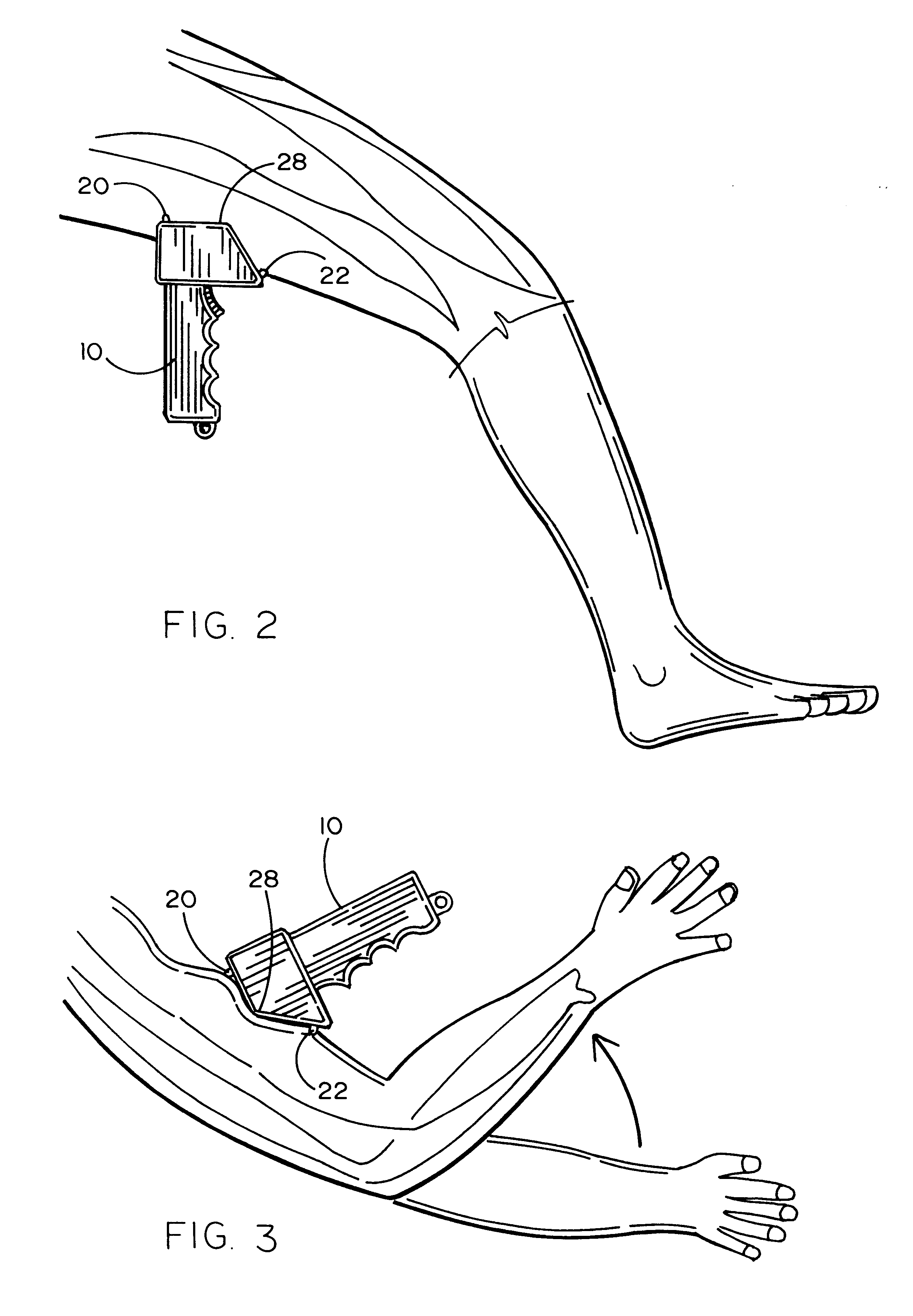
This embodiment of the invention provides a launchable projectile in the form of wire-tethered darts in a conventional cartridge that is received in a cartridge receptacle 18 in head portion 12. More pertinent to the inventive aspect of the disclosed stun gun apparatus, is a pair of electrical contacts 20 and 22 projecting above respective surfaces 21 and 23 of the head portion 12. The handle portion is also provided with a battery compartment cover 24 and a wristband holder 26.

The shape of head portion 12 as seen in FIG. 1 is trapezoidal. This trapezoidal shape is characterized by a foreshortened top surface 21 (as compared to the bottom of head port...


PUM


Abstract

A stun gun having an electrically insulated protuberance that extends to a height above the line between the vertical terminations of the exposed electrical target contacts. Before the weapon's target probes can be brought in contact with the target, the insulative protuberance compresses the target's muscle. This action shortens the length of the muscle while increasing the area of tissue involved in a subsequent shocking discharge. This, in turn, increases the likelihood of a sustained involuntary flexing or extending contraction of the muscle. A rectangular ammunition bay may be placed in the weapon with a portion of one partially exposed probe touching the ammunition's negative contact and a portion of the other partially exposed probe touching the ammunition's positive contact. In the event of a ballistic deployment failure, without the addition of any circuitry, the weapon can still act as a manual contact weapon.

Description

1. Field of the InventionThis invention relates to a class of weapons for immobilization and capture which are referred to as "stun guns" and more specifically to a subclass of those weapons having a pair of electrically opposed target probes between which a current is generated to disable a human or other animal target when the probes are manually placed in contact with such target and the weapon is energized.2. Prior ArtManually connected electrical discharge weapons are intended to be hand held, concealable upon the person, and conveniently portable. Accordingly, such a weapon's height is normally less than 7", its width is normally less than 2.75", and its depth is about 0.75". The target contacts are typically spaced about 2.5" apart along the weapon's width. The weapons shock with circuits similar to those described in U.S. Pat. No. 4,253,132, titled Power Supply For Weapon For Immobilization And Capture and issued to John Cover in February, 1981, for inclusion in stun guns wi...

Claims


Application Information

Patent Timeline
Patent Type & Authority Patents(United States)
IPC IPC(8): H05C1/00
CPCH05C1/00F41H13/0018
Inventor MCNULTY, THOMAS VI
Owner RESNICK BARNET
Why Eureka
Try Eureka