Semi-submersible vessel

a submerged vessel and submerged technology, applied in the field of submerged vessels, can solve the problems of many technical problems of vessel designers, existing offshore operations, services and resource exploration technology fails to adequately address the many challenges associated with deep water, and known technology fails to adequately address

Inactive Publication Date: 2001-07-17
HELIX ENERGY SOLUTIONS GROUP
View PDF87 Cites 7 Cited by
  • Summary
  • Abstract
  • Description
  • Claims
  • Application Information

AI Technical Summary

Benefits of technology

It is therefore an object of the present invention to provide an improved semi-submersible vessel which does not require cross-bracing.
In another aspect of the present invention, there is provided a method for installing product comprising the steps of securing a loaded reel to the underside of a semi-submersible vessel, attached a lead line to the product of the reel, unspooling the product with the lead line, associating the product with a dead weight and lowering the dead weight to an installation site. In a preferred embodiment, two or more reels may be secured to the underside of a semi-submersible vessel, whereby either product may be continuously installed from a first and a second reel or two different products may be simultaneously installed. Preferably, the moon pool of the semi-submersible is enlarged to a size which allows for materials and other apparatus to be directly loaded from the underside of the vessel from a transport vessel or other feed source.

Problems solved by technology

The demands of deep water exploration and installation present many technical problems for vessel designers.
Existing technology used in offshore operations, services and resource exploration fails to adequately address the many challenges associated with deep water.
For example, rapid transit speed combined with installation and removal capabilities are desired features which are inadequate in existing designs.
Service and maintenance needs related to equipment placed in extreme depths, e.g., flow lines, jumpers, tie-ins and service umbilicles, presents significant issues which known technology fails to adequately address.
Cross brace support members, while essential to the structural integrity of traditional designs for semi-submersible vessels, create undesirable characteristics.
For example, cross brace support members create hydrodynamic drag and create problems related to underslung loads.
In addition, cross brace support members preclude easy and efficient loading and reloading of vessels.
Such an alternative design fails to fully address performance and operational issues.
Canadian Patent No. 1,279,531 discloses a semi-submersible vessel without any cross bracing, but fails to disclose means which would adequately support such a structure.

Method used


Image

  • Semi-submersible vessel
  • Semi-submersible vessel
  • Semi-submersible vessel

Examples


Embodiment Construction

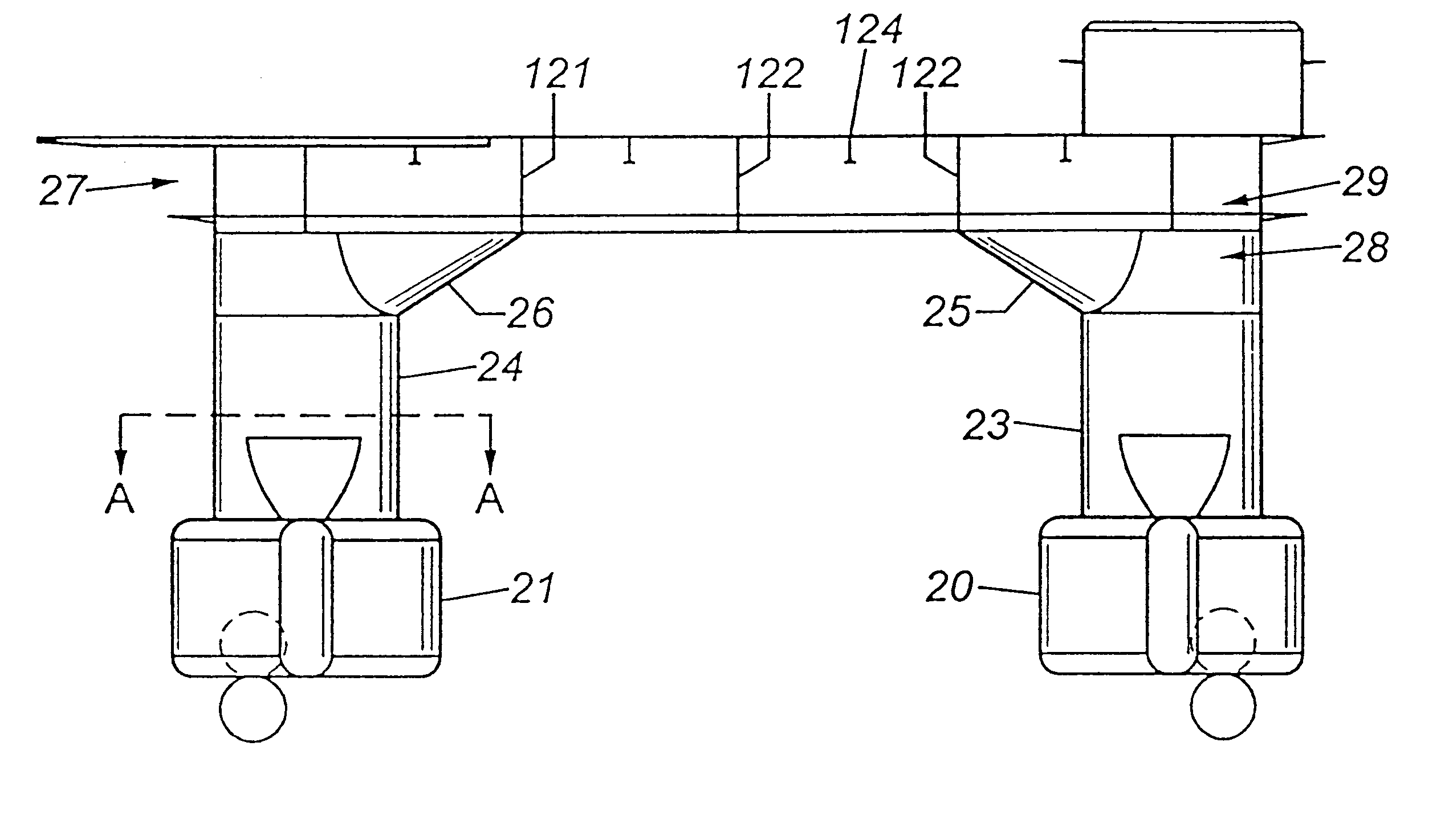
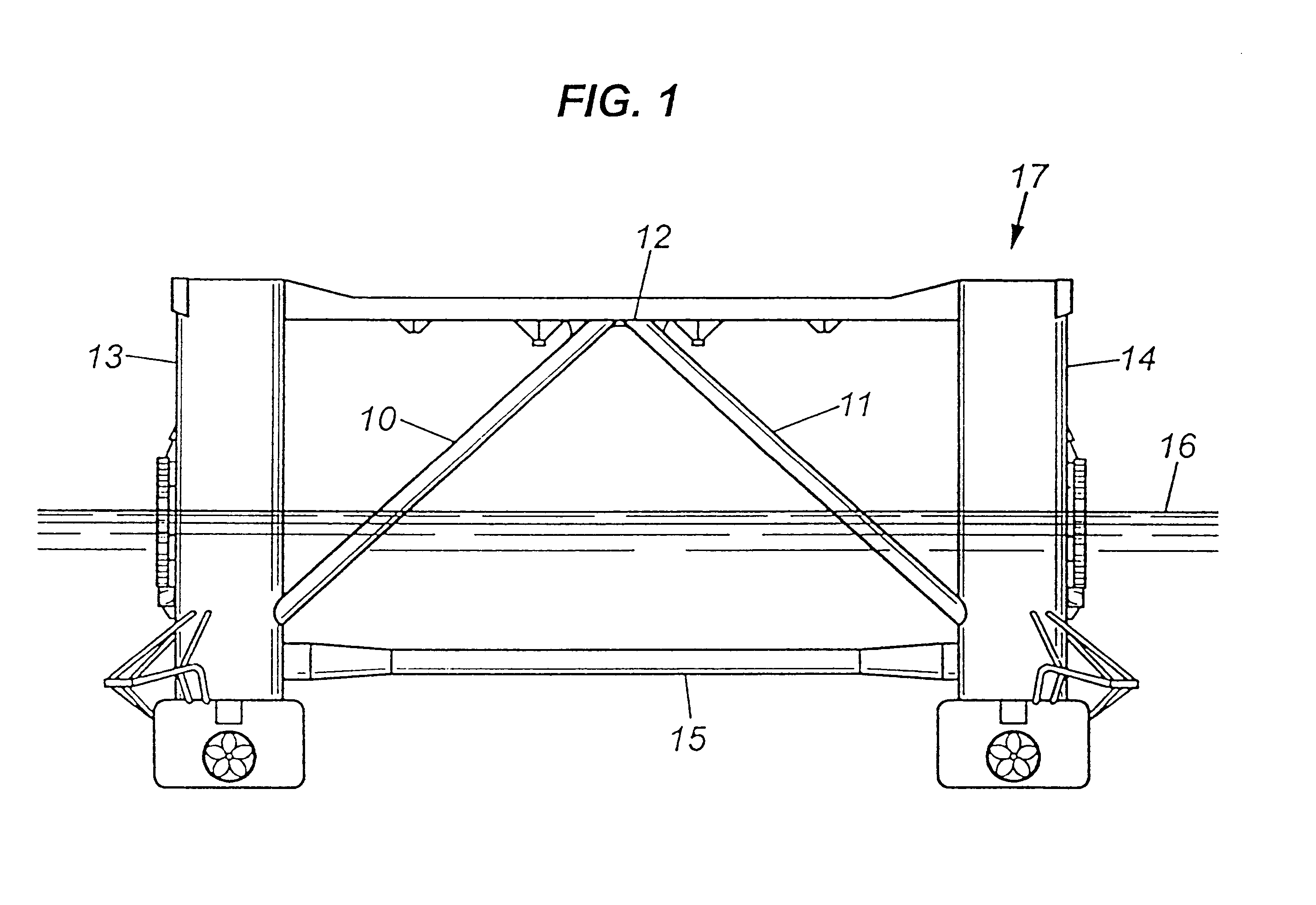
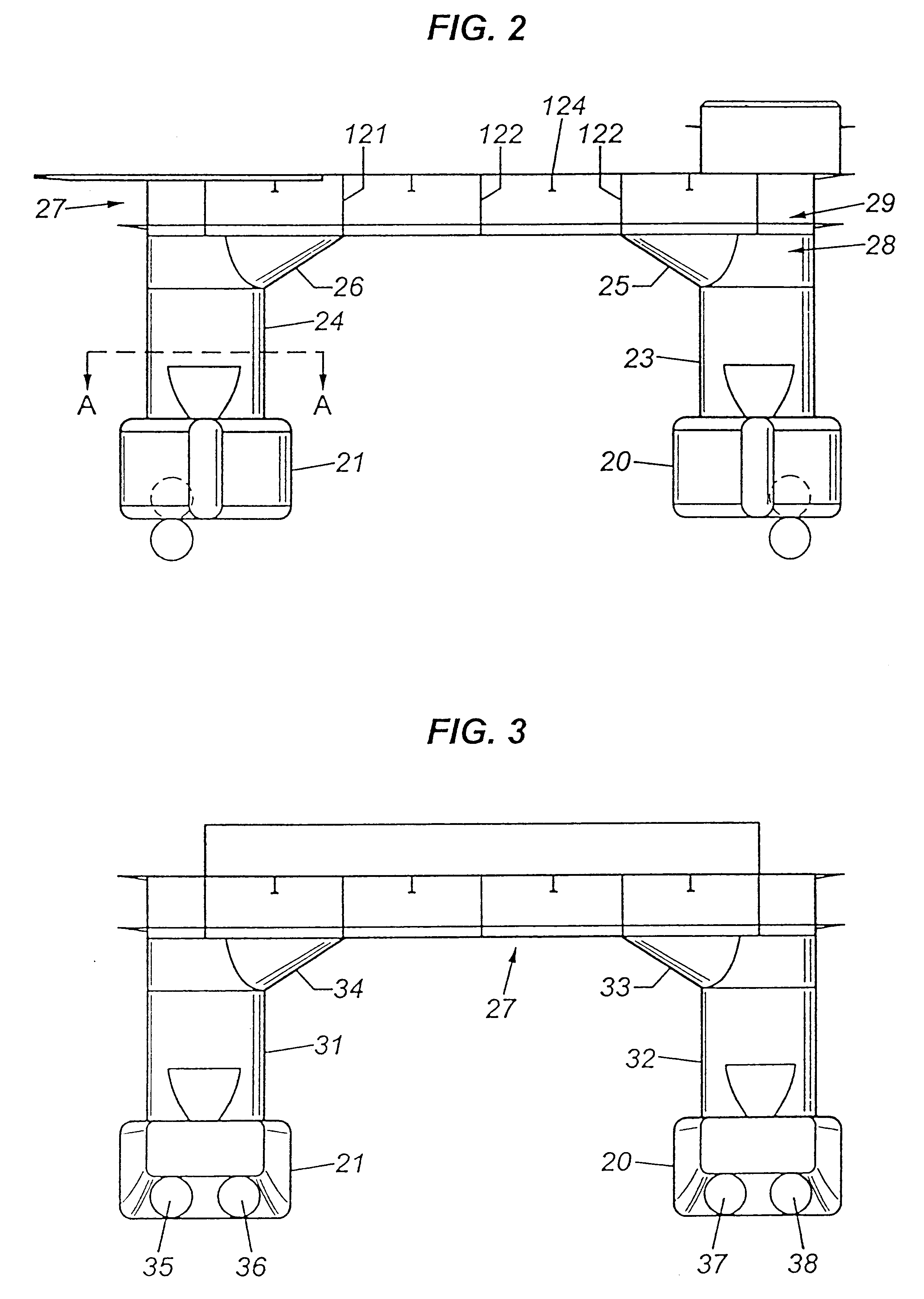
The present invention provides a mobile vessel designed to accomplish a variety of functions at an offshore site. In contrast to known vessel designs and improvements, the present invention provides a stable semi-submersible vessel design with expanded capabilities, without support members which impair hydrodynamic properties and the useful operation of such a vessel.

As discussed above, depleted energy resources and increased energy demand has created a need for a deep water resource exploration and service vessel. The usefulness of existing semi-submersible vessel designs is somewhat limited because prior designs have unnecessarily limited transit speeds and the normal operations of such vessels.

The primary structural forces on a semi-submersible vessel are in the transverse direction. As used herein, transverse forces are those forces with a direction generally perpendicular to the pontoons of a semi-submersible vessel. In traditional semi-submersible vessels, a truss system is us...


PUM


Abstract

An uncrossed-braced, column stabilized semi-submersible and improved methods of operation of the same are disclosed. The semi-submersible vessel provides necessary strength to resist hydrodynamic forces via a unitized support system. Improved elliptically shaped columns, haunch supports and reinforcing members provide stability and resist transverse forces. A skirt design minimizes the reduced stability at the transition point. Improved deck designs reduce environmental impacts and provide additional support against transverse forces.

Description

BACKGROUND OF INVENTIONThis invention relates to a semi-submersible vessel used in connection with offshore operations, services and resource exploration. More particularly, this invention relates to (1) a hybrid of a column stabilized semi-submersible vessel which expands the useful operations and life thereof and (2) improved methods of performing offshore operations, services and resource exploration therewith.Increased energy demands and decreased energy resources have created a need to explore and produce resources from deeper offshore areas. The demands of deep water exploration and installation present many technical problems for vessel designers. Existing technology used in offshore operations, services and resource exploration fails to adequately address the many challenges associated with deep water.Placement of equipment in deep waters necessitates new methods of installation, maintenance, repair and removal. For example, rapid transit speed combined with installation and...

Claims


Application Information

Patent Timeline
IPC IPC(8): B63B1/10B63B35/00B63B35/04B63B1/00B63B35/03B63B1/12B63B35/44B63B43/04
CPCB63B1/107B63B27/02B63B27/30B63B35/03B63B35/04B63B35/003B63B43/04B63B27/19
Inventor KRATZ, OWENKETTING, HANKKELLOGG, STANLEY GROEDECKE
Owner HELIX ENERGY SOLUTIONS GROUP
Why Eureka
Try Eureka