Winder for sheet material

a technology of sheet material and winding machine, which is applied in the direction of thin material handling, article delivery, filament handling, etc., can solve the problems of large production cost, inability to meet the needs of production, and long film length upon roll changing

Inactive Publication Date: 2001-07-17
FUJI TEKKO
View PDF5 Cites 24 Cited by
  • Summary
  • Abstract
  • Description
  • Claims
  • Application Information

AI Technical Summary

Problems solved by technology

As a consequence, the winding machine is inevitably large-sized as the winding diameter is larger, and the production cost is vastly increased, as well.
Further, when the distance between the winding shafts is larger, the path length of the film upon roll changing is longer, which is responsible for the occurrence of neck-in and wrinkling of a film susceptible to extension.
Again where the di...

Method used


Image

  • Winder for sheet material
  • Winder for sheet material
  • Winder for sheet material

Examples


Embodiment Construction

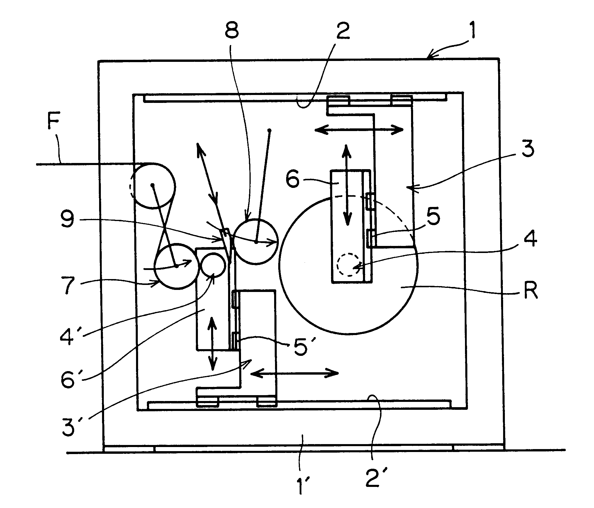
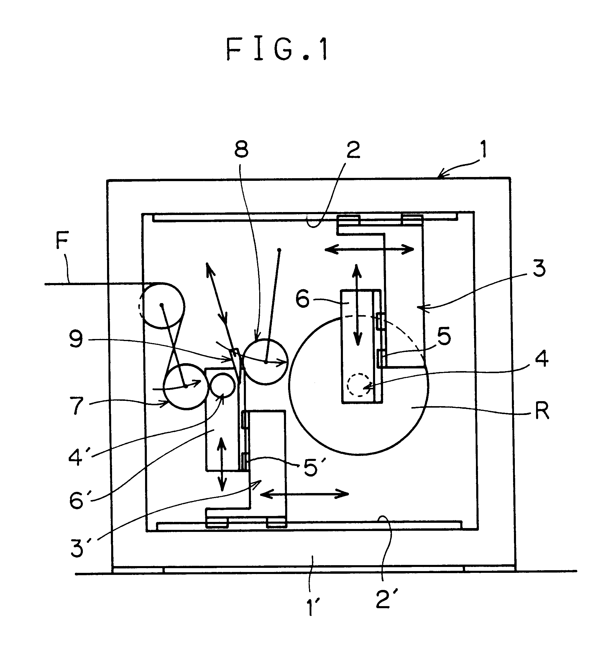
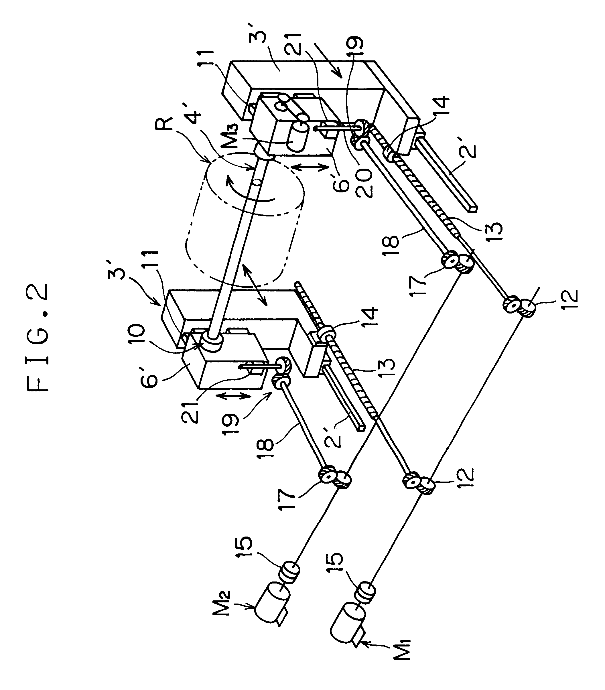
Referring to FIGS. 1 and 2, the reference numerals 1,1' designate upper and lower main frames, which are formed integrally as a rectangular frame, as viewed in FIG. 1, and positioned in diametrically opposed manner at a required distance spaced apart. At the inner sides of the upper and lower main frames at the right and left hands, there are disposed linear rails 2,2'. Upper-stage winding frames 3 are disposed to be suspended from the linear rail 2 to be slidingly movable back and forth along the upper main frame 1 at least between a winding position at the left hand in FIG. 1 and a removal position of a full roll at the right hand in FIG. 1 whereas lower-stage winding frames 3' are disposed to face upwards to be slidingly movable back and forth at least between the winding position at the left hand in FIG. 1 and the removal position of a full roll at the right hand in FIG. 1.

The upper-stage winding frames 3 and the lower-stage winding frames 3' are defined with linear rails 11 at ...


PUM


Abstract

A two-shaft linear motion type winder for winding up a sheet material, e.g. a film is provided, which can eliminate the occurrence of any mechanical loss by simplification of a transission device, shorten the path distance of the film upon roll changing, prevent the neck-in and wrinkling of the film and reduce vastly the roll changing cycle. It comprises at least a pair of upper-stage winding frames having holders for an upper winding shaft, suspended from an upper main frame to be slidingly movable back and forth in a given area; and a pair of lower-stage winding frames having holders for a lower winding shaft, disposed on a lower main frame to face upwards so as to be slidingly movable longitudinally in a given area. The holders for the upper and lower winding shafts are capable of ascending and descending vertically; and each of the upper-stage and lower-stage winding frames, upon full winding, move the one winding shaft with a full roll from a winding position to a removal position of the roll while shifting the other winding shaft to the winding position thereby enabling the roll changing; each of the frames and holders being movable individually without mutual interference.

Description

1. Field of the InventionThis invention relates to a winder for a sheet material such as a film or the like, and more particularly, to a multi-shaft linear motion type winder for winding up a film or the like without using a turret.2. Description of the Related ArtWhen a film being fed from the film making step is wound up on a winding core in a given length, roll changing is performed from the core having thereon the wound-up film to a new winding core.Hitherto, a two-shaft (A,B) turret T as shown in FIGS. 4A to 4D, on which one shaft with fully-wound roll and the other shaft for a new winding core are installed together, or a multishaft turret has been used, and consequently, the roll changing work has been conducted by turning the turret T every time the winding process is finished.That is, in the state illustrated in FIG. 4A, a shaft A is in the course of winding while a shaft B is being attached with a new winding core. A film F is wound via a guide roller onto a winding core o...

Claims


Application Information

Patent Timeline
IPC IPC(8): B65H19/30B65H19/22B65H19/26
CPCB65H19/305B65H19/223
Inventor UEYAMA, MINORU
Owner FUJI TEKKO
Why Eureka
Try Eureka