
Retaining element for an implant and ampoule for preserving said implant

a technology of ampoule and retaining element, which is applied in the field of ampoule for preserving implants, can solve the problems of insufficient grip of implants by screw covers or connecting elements, high cost of ampoules, and inability to reliably hold implants, etc., and achieves the effect of reducing contamination or damage to the implant surface, ensuring stability, and ensuring stability

Inactive Publication Date: 2001-07-17
STRAUMANN HLDG AG
View PDF9 Cites 110 Cited by
  • Summary
  • Abstract
  • Description
  • Claims
  • Application Information

AI Technical Summary

Benefits of technology

The holding element of the invention simplifies handling of the generic implants during production and implantation itself. An implant can be taken hold of on the holding element and manipulating members and screwing-in tools can be attached without problems and released again. In combination with the holding element, the effect is achieved that the ampoule does not have to consist of the same material as the implant or contain a specifically protective insert made of the implant material. The risks of contamination or damage to the implant surface are considerably reduced a...

Problems solved by technology

These ampoules are to some extent very expensive, as the tool components are generally only used once.
Furthermore, handling these ampoules often requires a relatively large number of operations, and in addition external screwing-in tools are also required.
Finally, it is doubtful whether the implants are gripped sufficiently reliably by the screw covers or the connecting elements.
Suitable external tools are used to grip the implant, while on the ampoule itself there are no means whatsoever which facilitate and make more reliable the removal of the implant from the ampoule and transportation to the site of implantation.
The instruments attached while the implants are being introduced into the bone are unsuitable as manipulating members during the overall production process of the implants; separate holders have to be used for this purpose.

Method used


Image

  • Retaining element for an implant and ampoule for preserving said implant
  • Retaining element for an implant and ampoule for preserving said implant
  • Retaining element for an implant and ampoule for preserving said implant

Examples


Embodiment Construction

The following statement applies to the whole of the rest of the description. If, for the sake of clarity of the drawing, a figure contains reference numerals which are not explained in the immediately associated text of the description, reference is made to where they are mentioned in previous descriptions of figures; for the sake of clarity, repeated designation of components in following figures is generally dispensed with, as long as it can be clearly seen from the drawings that these are "recurring" components.

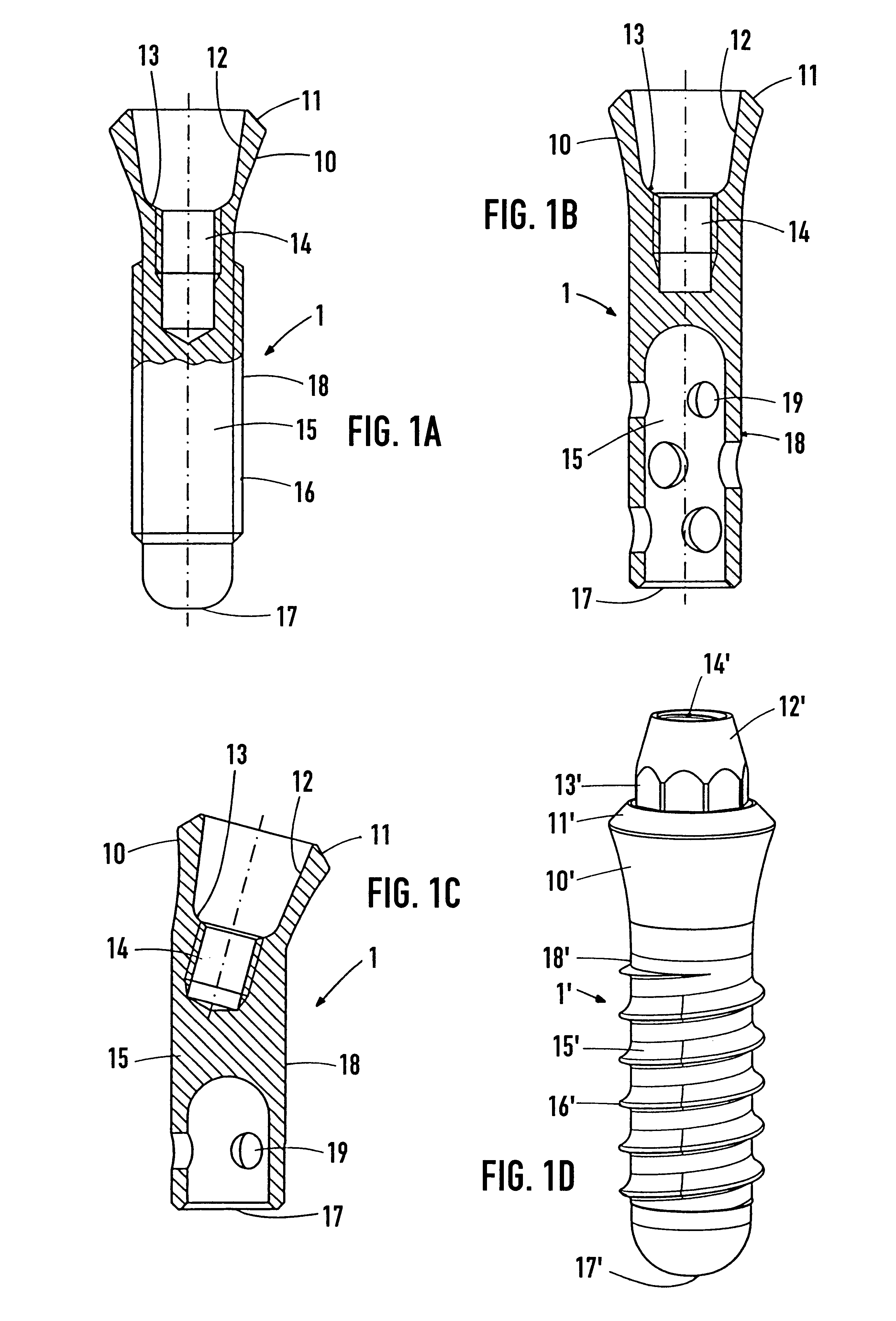
FIG. 1A

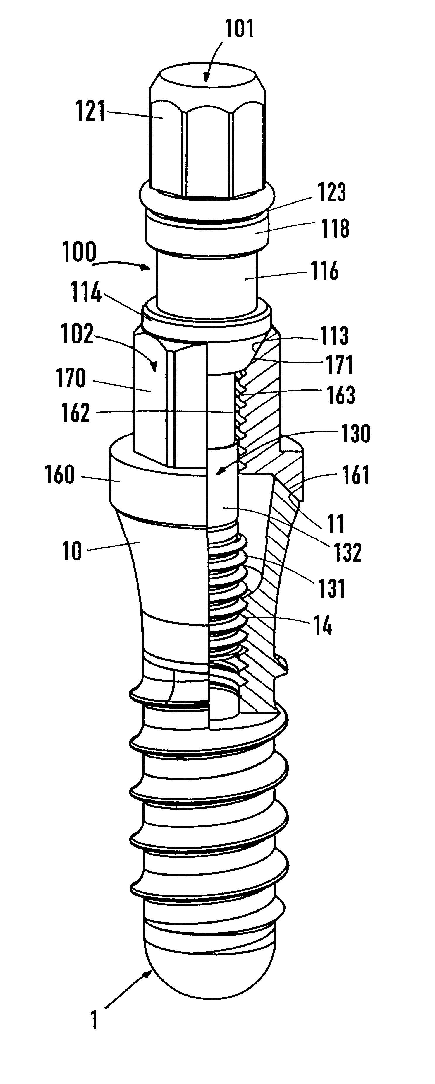
The implant 1 of the first type in this figure is in the form of a solid screw and, at the top, has the implant head 10 which is widened in the form of a trumpet and at the top ends with the conical implant shoulder 11. The implant shoulder 11 surrounds a conical bore 12 which opens out here, widens outwards and as a threaded bore 14 continues further downwards beneath the base of the bore 13. Towards the apical end, the root part 15, which has the external screw th...


PUM


Abstract

The proposal is for a holding element (100) which can be screwed into the internally threaded bore (14) of the implant (1) even during production of the latter and can thus be used to grip or hold the implant for the following production phases. Furthermore, the holding element (100) serves to fix an implant (1), which is screwed thereto, inside an ampoule (200) and for the application of a screwing-in tool for implantation. The particular feature of the ampoule (200) lies in the fact that it has a large-area, lateral cutout (231) in the casing and also a fixing part (210) for accommodating the holding element (100) in a clamped manner. The implant (1) can thus be pulled laterally out of the ampoule (200). The devices facilitate handling of the implant (1) during production and insertion into the bone.

Description

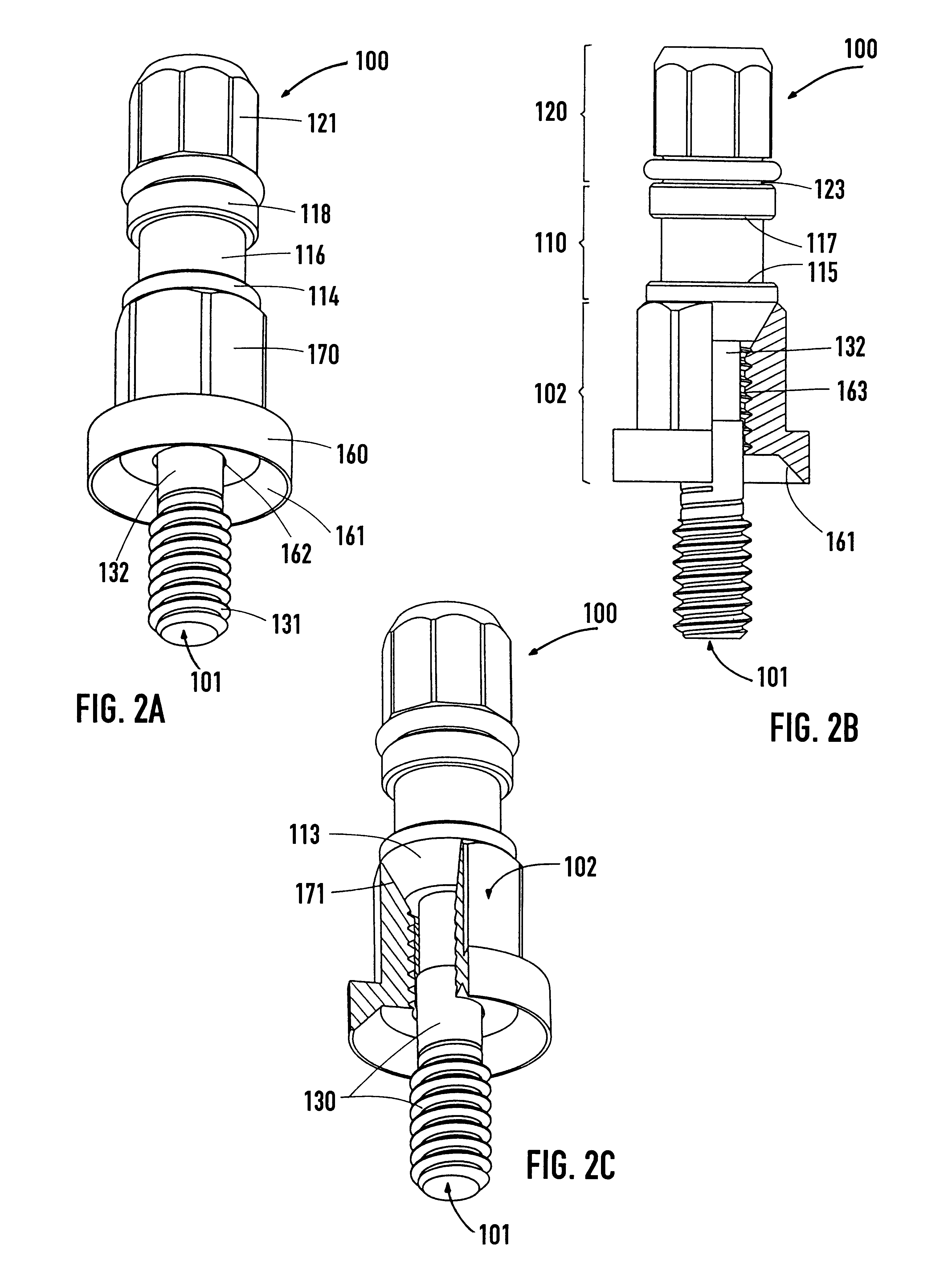
APPLICATION AREA OF THE INVENTIONThe present invention relates to a holding element for an implant, primarily in screw or cylinder form. A first type of implant which may be considered has a bore which at least in principle emerges axially on the implant head and has an internally threaded section. The mouth of the bore is surrounded by an implant shoulder, which forms the upper end of the implant. The second type of implant which is suitable has a segment which projects above the implant shoulder and has an internally threaded section. The segment has a predominantly polygonal or conical outer contour. Such implants are used, for example, in the dental sector or in bone surgery. The implant is intended to be inserted--i.e. screwed or pressed--into a receiving bore which has been prepared in the bone. This depends on whether the receiving bore has an internal screw thread or the implant has a self-tapping thread or the implant has no thread at all. Furthermore, the invention relates...

Claims


Application Information

Patent Timeline
IPC IPC(8): A61C8/00
CPCA61C8/0087
Inventor SCHMUTZ, WERNERSIMPSON, JAMES PERCIVAL
Owner STRAUMANN HLDG AG
Learn More