
Devices with micro-filters and micro-choppers for dynamic selection of colours and images

a technology of microfilters and microchoppers, which is applied in the direction of color television details, instruments, optics, etc., can solve the problems of cost of both base materials and required technologies, difficulty in aligning, and bending of beams, and achieves the effect of low cos

Inactive Publication Date: 2001-07-17
CENT RICERCHE FIAT SCPA
View PDF8 Cites 53 Cited by
  • Summary
  • Abstract
  • Description
  • Claims
  • Application Information

AI Technical Summary

Benefits of technology

In the present invention, the problems of the prior art are overcome by using a matrix of micro-filters and a matrix of electrostatic micro-choppers. The materials are conventional and the technologies required for carrying out the invention are of low cost.

Problems solved by technology

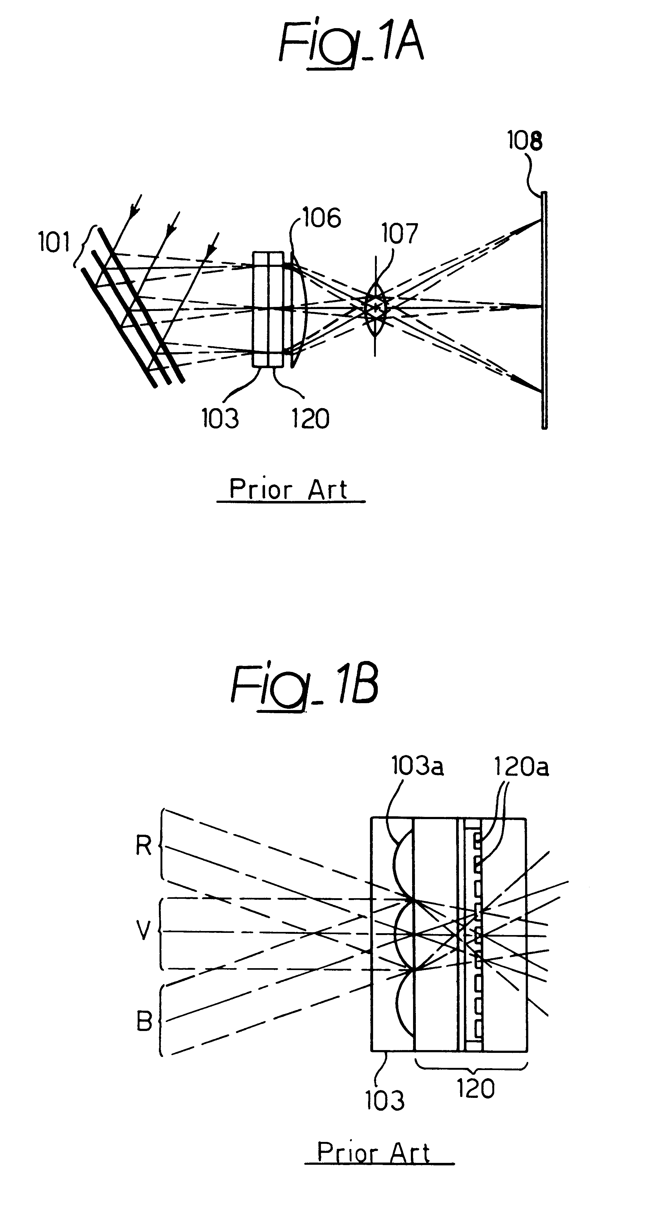
This type of projection system has the advantages of using the whole spectrum of the light source, but is expensive and bulky, since it requires three LCDs and dichroic lenses; furthermore it is difficult to align.
In this solution there are still more problems, since it requires a relatively collimated light beam, since otherwise the dichroic filters would operate in a non efficient way and the use of the dichroic mirrors, which are expensive and can operate only in reflection, would cause a bending of the beam.
In all cases making use of liquid crystals, there is the problem of the cost both of the base materials and the required technologies.
Another problem is associated to the limited field of temperatures of use; as a matter of fact, liquid crystals cease to operate outside a range between -20.degree. C. and +80.degree. C.

Method used


Image

  • Devices with micro-filters and micro-choppers for dynamic selection of colours and images
  • Devices with micro-filters and micro-choppers for dynamic selection of colours and images
  • Devices with micro-filters and micro-choppers for dynamic selection of colours and images

Examples


Embodiment Construction

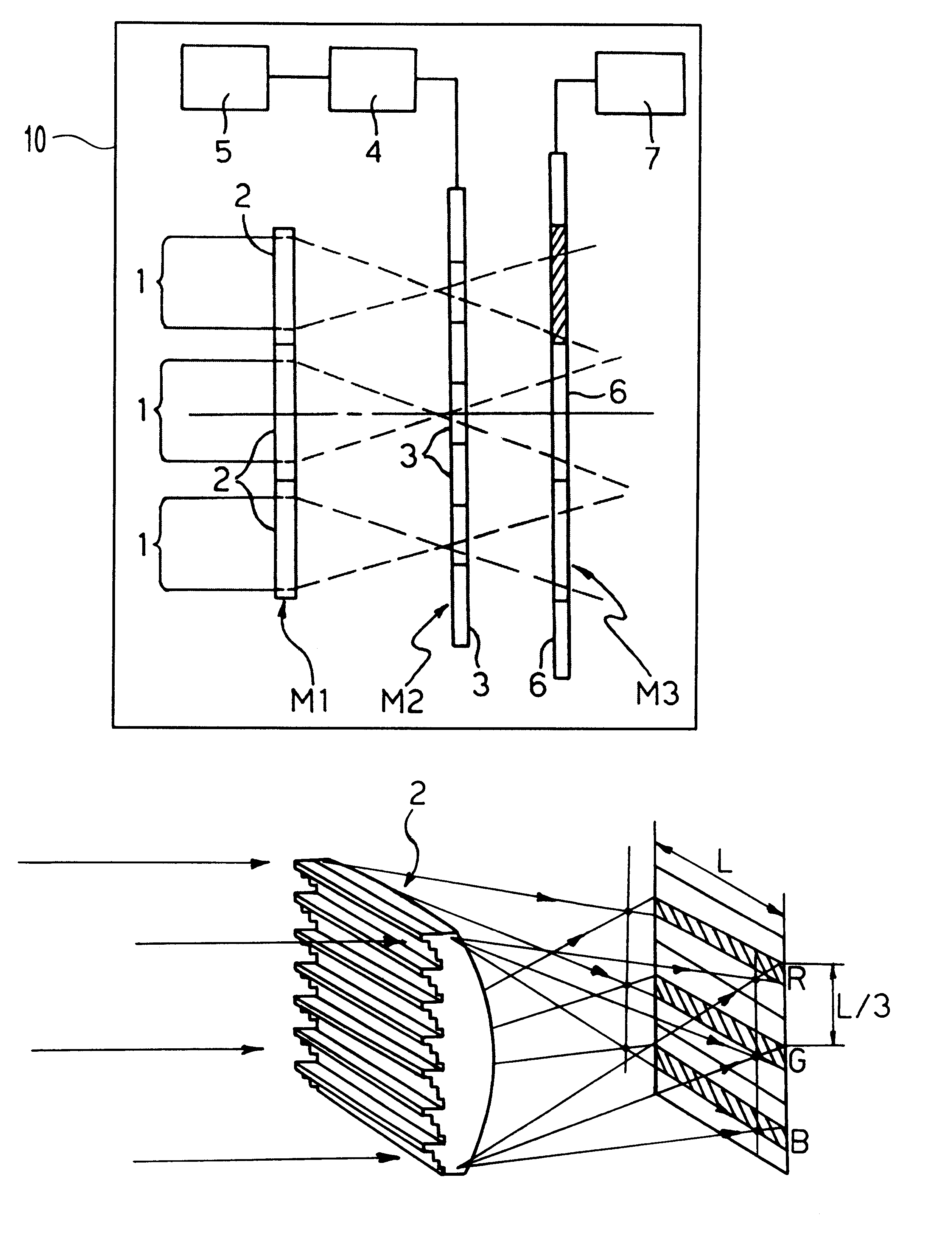
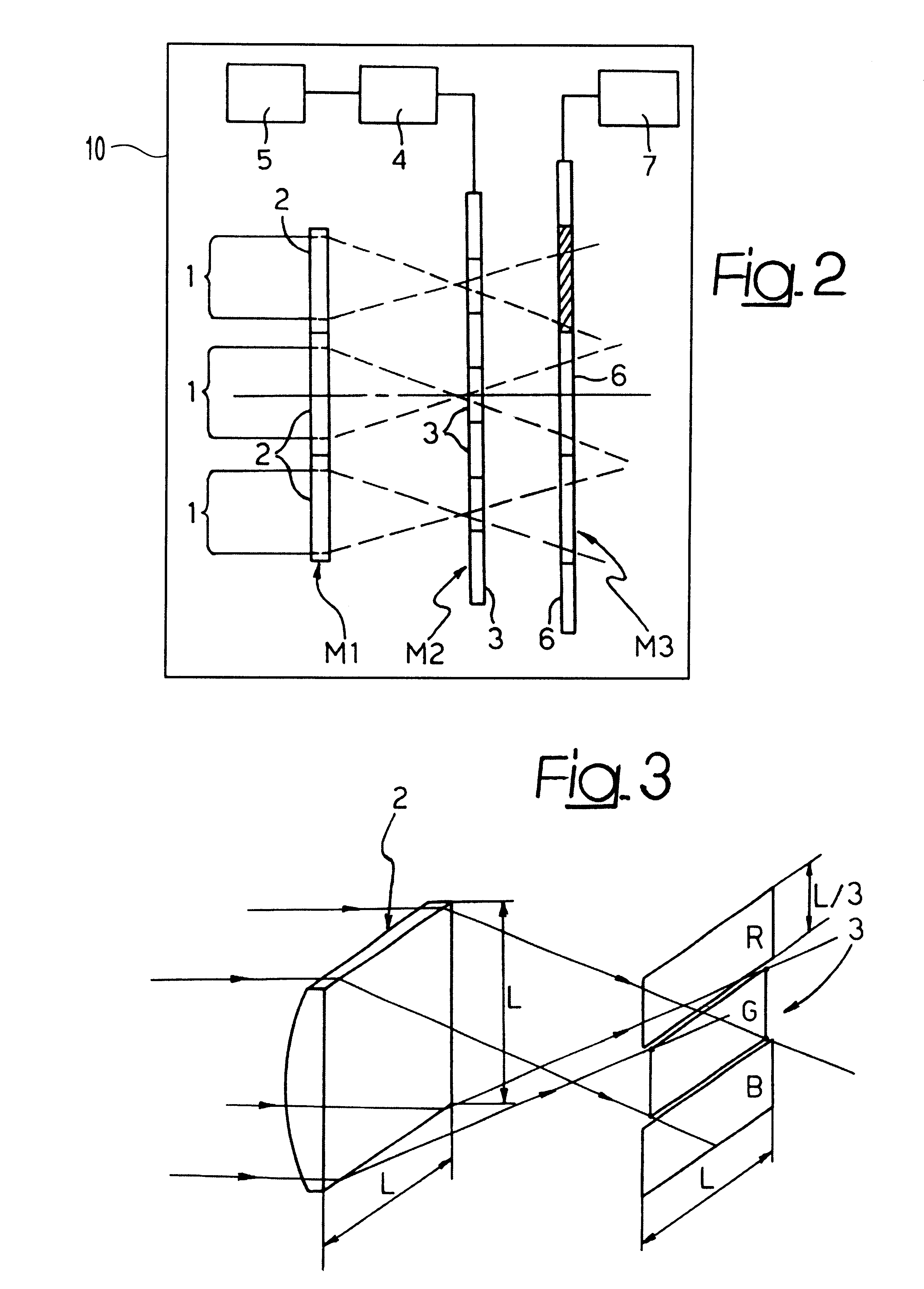
Item 10 in FIG. 2 represents one embodiment of a device for dynamic selection of colors and images.

With reference to FIG. 2, a polychromatic light beam 1 is intercepted by a matrix M1 of microlenses 2. Each microlens 2 causes the intercepting portion of light beam to converge onto a matrix M2 of microfilters 3 which selects the desired colors or images by a translation applied to the matrix M2 by an actuator device 4 controlled by a control processing unit 5. The details of construction relating to the actuator device 4 and the way by which the matrix M2 is displaced in its plane with respect to the microlens matrix M1 are not shown herein, since these means may be provided in any known way and the deletion of these details from the drawings renders the latter simpler and easier to understand. Once it has passed through microfilters 3 the light beam reaches a matrix M3 of microchoppers 6, whose opening and closing movements are controlled by a control processing unit 7.

The size of m...


PUM

PropertyMeasurementUnit
thicknessaaaaaaaaaa
colorsaaaaaaaaaa
transparentaaaaaaaaaa

Abstract

The radiation beam emitted by a polychromatic source of finite dimension is incident onto an array of microlenses which have the function of converging and dividing the beam into a plurality of microbeams directed towards a matrix containing colored microfilters. Once the microfilters have been passed, the radiation reaches a matrix of microchoppers which can be selected independently from each other by a controller, for generating images.

Description

The present invention relates to the field of optical devices for dynamic display of images.PRIOR ARTDevices of this type are known which make use of matrix of cells, each of which is able to change its state. Liquid crystal display devices (LCD) having polarizing filters and display devices with micro-mirrors are known. There are two types of liquid crystal projection systems, namely the systems with three LCDs and those with a single LCD. The systems with three LCDs include a source of white light and lenses for dividing the light beam in order to generate three colored beams of the three primary colors red, green and blue; three monochromatic LCDs change the three colored beams into three images. These images are superimposed on each other by three dichroic elements and are finally projected on a screen by a lens. This type of projection system has the advantages of using the whole spectrum of the light source, but is expensive and bulky, since it requires three LCDs and dichroic...

Claims


Application Information

Patent Timeline
Patent Type & Authority Patents(United States)
IPC IPC(8): G02B5/22G02B3/00G02B5/18G02B26/08
CPCG02B3/0056G02B5/1814H04N9/3197H04N9/3117G02B5/22
Inventor PERLO, PIEROREPETTO, PIERMARIOSINESI, SABINO
Owner CENT RICERCHE FIAT SCPA
Learn More