
Dynamic overflow protection for finite digital word-length multi-carrier transmitter communications equipment

Inactive Publication Date: 2001-07-17
RATEZE REMOTE MGMT LLC
View PDF7 Cites 55 Cited by
  • Summary
  • Abstract
  • Description
  • Claims
  • Application Information

AI Technical Summary

Problems solved by technology

A practical cellular system has limited power capabilities.
However, in a system that uses a digital combiner in the transmit path, such a method presents difficulties associated with possible combiner overflow.
Failure to address this issue can result in compromised transmitted signal quality.
Digital overflow is undesirable because it can destroy the transmission signal to noise ratio, distort the transmitted signals and even possibly disable the entire BTS.
Simply limiting the digital amplitude of all carriers input into the combiner will not provide a satisfactory solution to the foregoing combiner overflow problem since the resultant combiner digital output will often be significantly less than required to drive digital to analog conversion circuitry to full scale.
However, power amplifiers always have limited gain and are often designed to operate most efficiently near their limit for economic reasons.
Second, even assuming the power amplifier can supply sufficient power to provide the mobile user with the desired power level, a reduction in digital signal amplitude output from the combiner will result in degraded signal quality because the carrier to noise level will be fixed at the output of the Analog to Digital (D / A) converter.
Therefore, additional amplifier gain would not achieve the same benefit that maximizing the input digital word to the combiner would achieve.
Fortunately, a theoretical worst case power configuration is unlikely to occur.
In addition, most carriers will not be at maximum power because in an actual deployment it is not expected that all carriers will be operating at or near full power.

Method used


Image

  • Dynamic overflow protection for finite digital word-length multi-carrier transmitter communications equipment
  • Dynamic overflow protection for finite digital word-length multi-carrier transmitter communications equipment
  • Dynamic overflow protection for finite digital word-length multi-carrier transmitter communications equipment

Examples


Embodiment Construction

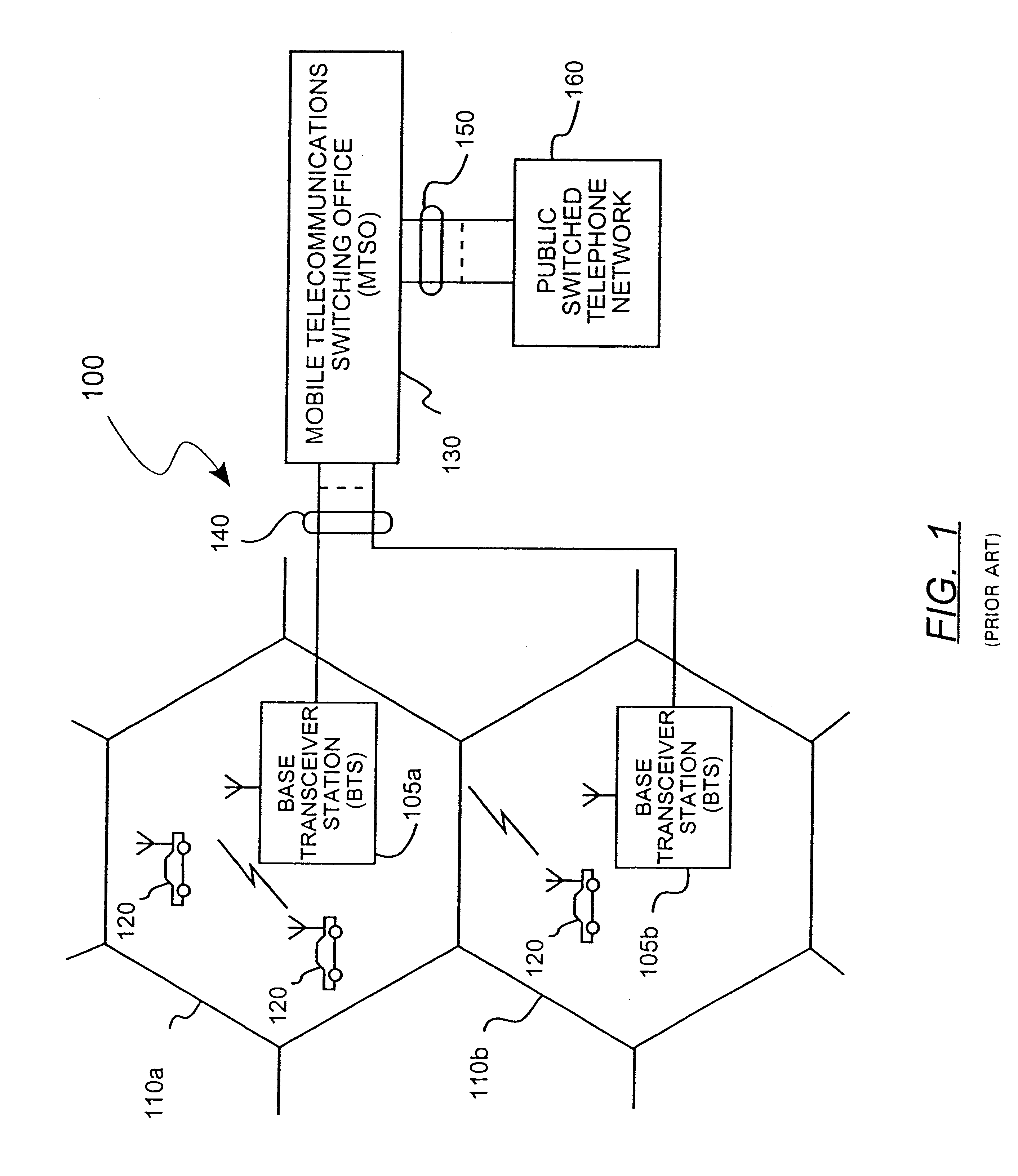
FIG. 1 illustrates a conventional cellular phone system. As illustrated in FIG. 1, the cellular phone system 100 includes a plurality of cells 110a, 110b, a plurality of mobile units 120, a plurality of base transceiver stations (BTS) 105a, 105b, communication lines 140, a mobile telecommunications switching office (MTSO) 130, an interface 150 and a switched telephone network 160.

The cellular phone system 100 has a fixed number of channel sets distributed among the BTS 105a, 105b serving a plurality of cells 110a, 110b arranged in a predetermined reusable pattern. The mobile unit 120, in a cell 110a or 110b, communicates with the BTS, 105a or 105b, respectively, via radio frequency (RF) means.

The BTS 105a, 105b communicate with the MTSO 130 via communication lines 140. The MTSO 130 communicates with the switched telephone network 160 via the interface 150. In the cellular phone system 100, the cell areas typically range from 1 to 300 square miles. The larger cells typically cover ru...


PUM


Abstract

A method and apparatus for power management that controls the overflow of a digital combiner used in the transmit path for a broadband transceiver station (BTS) is disclosed. Power is managed by a digital word banking agent which is a part of the BTS system software. If a new channel request is received, the digital word banking agent determines if the request can be satisfied at the requested power level. Otherwise, the digital word banking agent determines if the channel request can be satisfied at a lower power request. The digital word banking agent also manages active channels by reclaiming power from channels requiring less power and / or by allocating more power to the channels requesting more power. If the digital word banking agent cannot satisfy a request, the digital word banking agent will queue the request for submission at a later time in the event that additional power becomes available.

Description

1. Field of the InventionThis invention relates to a method for managing the size of a digital word representing a signal amplitude in any digital system having finite word length processing capacity that digitally combines more than one signal into a single composite signal. More specifically, the invention relates to a power management system in a base station transceiver system which uses a digital combiner in the transmit path to combine digital signals to control combiner overflow.2. Description of the Relevant ArtA conventional cellular phone system includes a plurality of cells, mobile units, a plurality of base transceiver stations (BTS), communication lines, a mobile telecommunications switching office (MTSO), an interface and a switched telephone network. A fixed number of channel sets are distributed among each BTS which serves a plurality of cells, arranged in a predetermined reusable pattern. The mobile unit, in a cell, communicates with the BTS, via radio frequency (RF...

Claims


Application Information

Patent Timeline
IPC IPC(8): H04B7/005
CPCH04W52/343H04W52/50H04W52/346Y02B60/50
Inventor SCHMUTZ, THOMAS R.
Owner RATEZE REMOTE MGMT LLC
Learn More