
Slow opening gas valve

a gas valve and slow technology, applied in the field of gas control, can solve the problems of excessive gas build-up in the combustion, rough and/or audible ignition, and inability to achieve audible ignition,

Inactive Publication Date: 2001-07-24
EMERSON ELECTRIC CO
View PDF9 Cites 56 Cited by
  • Summary
  • Abstract
  • Description
  • Claims
  • Application Information

AI Technical Summary

Problems solved by technology

In many of these gas valves, the amount of gas provided at the outlet at the time ignition takes place causes an undesirable audible ignition.
This audible ignition results from the rapid opening of the gas valve which causes excessive gas build-up in the combustion chamber of for example, a furnace, before ignition.
Thus, many of these "fast" open gas valves introduce too much gas before ignition takes place, thereby causing a very rough and / or audible ignition.
In addition to producing this undesirable audible ignition, these gas valves may create large flames upon ignition which could be dangerous.
In general, however, many of the known-gas valves do not provide a sufficient duration of continuous valve opening and further do not provide a smooth and gradual opening of the gas valve.
Additionally, these gas valves are generally complex in both design and operation, thereby increasing the likelihood of problems during operation.
Overall, these gas valves are relatively complex, which may result in problems with reliability.
Further, these gas valves fail to provide both a slow and continuous smooth opening of the valve.
Thus, an undesirable audible or rough ignition may still occur.

Method used


Image

  • Slow opening gas valve
  • Slow opening gas valve
  • Slow opening gas valve

Examples


Embodiment Construction

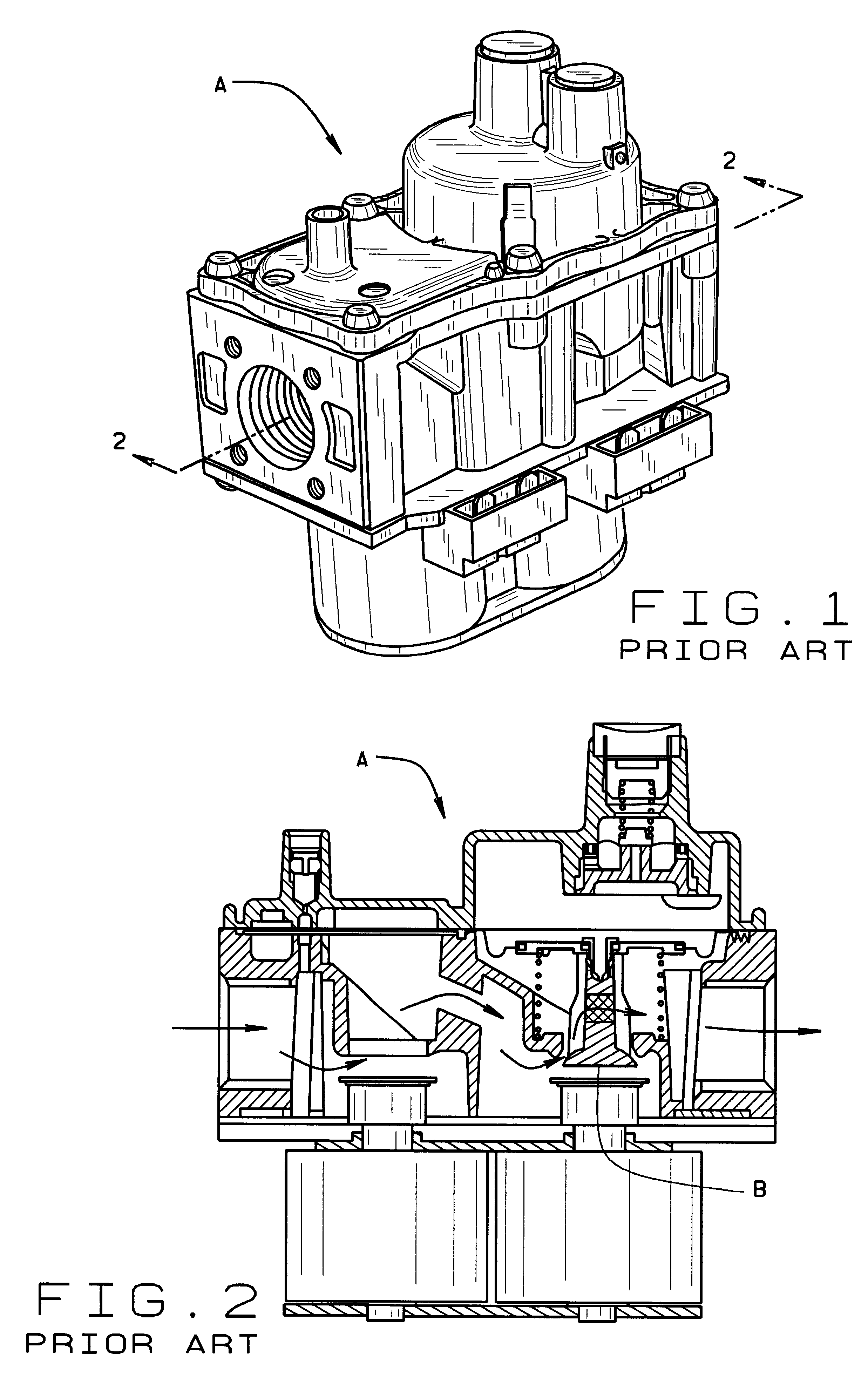
A typical prior art "fast" open gas valve is shown generally in FIGS. 1 and 2 and designated by reference character A. The prior art gas valve is not configured to provide a slow opening of valve member B and thereby typically causes an audible and / or rough ignition. In particular, the prior art gas valve does not provide an expansible auxiliary chamber connected to an expansible control chamber of the gas valve by a metering orifice.

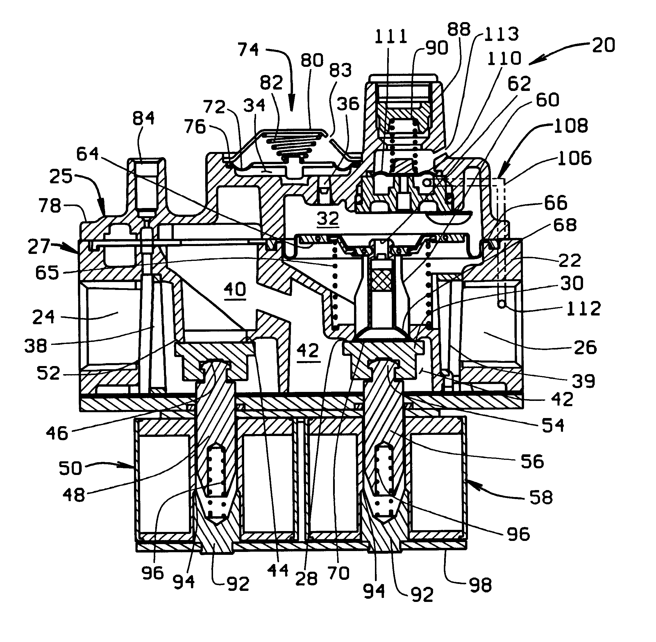
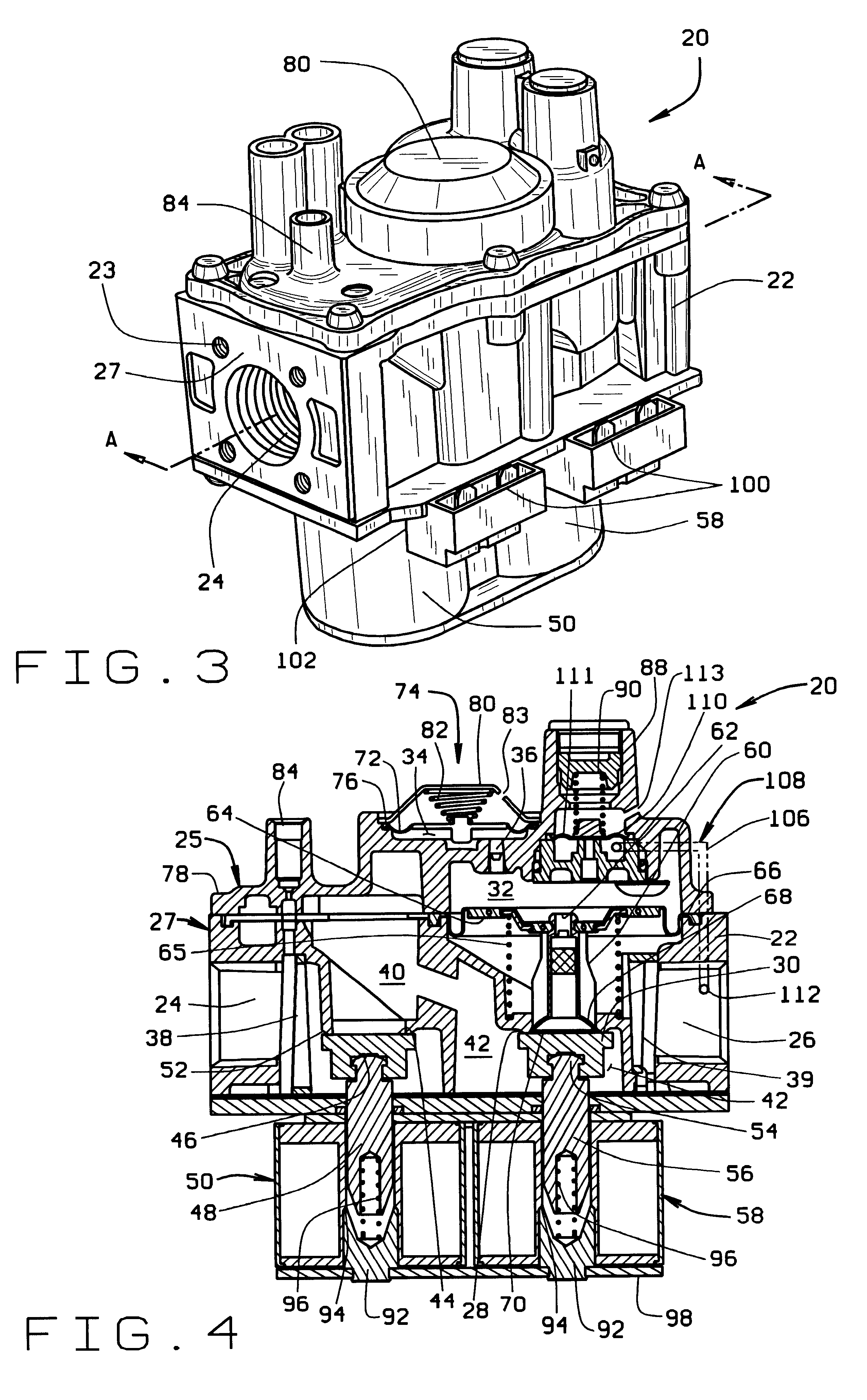
A slow opening gas valve providing for both continuously gradual and smooth opening of its valve member is designated generally by reference numeral 20 in FIGS. 3, 4, 5 and 6.

As shown in FIG. 4, the improved slow opening gas valve of the present invention, indicated generally as 20 in FIG. 4, is basically comprised of a valve housing 22, an inlet 24, an outlet 26, an outlet valve seat 28, an outlet valve member 30, and an expansible control chamber 32 connected to an expansible auxiliary chamber 34 by a metering orifice 36. The outlet valve seat 28, out...


PUM


Abstract

An improved slow opening gas valve providing for continuous gradual and smooth opening of the gas valve includes an expansible auxiliary chamber connected to an expansible control chamber by a metering orifice. The expansible auxiliary chamber slows expansion of the expansible control chamber, thereby slowing opening of the gas valve and allowing gas to ignite at a lower pressure with a much less audible sound. The gas valve is provided with a normally closed valve member for controlling flow of gas through the gas valve and a diaphragm forms a movable wall of the expansible control chamber that is operable upon expansion of the chamber to move the valve member to an open position. The expansible auxiliary chamber also comprises a movable diaphragm to control the opening of the gas valve and provide gas flow gradually and smoothly. In an alternate embodiment, a gas valve is configured to provide an initial gas flow through a bypass orifice in the closed valve member, which enables ignition of the gas at an optimum gas pressure instantly, followed by a gradual and smooth opening of the valve member. This arrangement provides a "step" function followed by the desired slow opening of the valve member.

Description

1) Field of the InventionThe present invention is directed to the field of gas controls, and in particular to an improved slow opening gas valve having an expansible auxiliary chamber connected to an expansible control chamber by a metering orifice to slow the expansion of the expansible control chamber and thereby slow the opening of the gas valve.2) Description of the Related ArtIt is well known that gas valves of the type to which the present invention relates are configured to provide gas at an outlet for ignition at a specific pressure level. In many of these gas valves, the amount of gas provided at the outlet at the time ignition takes place causes an undesirable audible ignition. This audible ignition results from the rapid opening of the gas valve which causes excessive gas build-up in the combustion chamber of for example, a furnace, before ignition. Thus, many of these "fast" open gas valves introduce too much gas before ignition takes place, thereby causing a very rough ...

Claims


Application Information

Patent Timeline
Patent Type & Authority Patents(United States)
IPC IPC(8): F16K31/42F16K31/12F16K31/06F23N1/00
CPCF16K31/0655F23N1/007F16K31/42F23N2035/20F23N2235/20Y10T137/1516Y10T137/7764Y10T137/7766Y10T137/87917
Inventor LOVE, JOHN J.SANTINANAVAT, MIKE C.
Owner EMERSON ELECTRIC CO
Learn More