Actuator, and timepiece and notification device using the same

a technology of actuators and timepieces, applied in the direction of generating/distributing signals, instruments, horology, etc., can solve the problems of inability of electromagnetic step motors to achieve such a reduction in thickness, and the thickness of conventional actuators is difficult to achieve a further reduction in thickness, so as to achieve the effect of reducing size and weight and thickness

Inactive Publication Date: 2001-07-24
SEIKO EPSON CORP
View PDF6 Cites 34 Cited by
  • Summary
  • Abstract
  • Description
  • Claims
  • Application Information

AI Technical Summary

Benefits of technology

In addition, it is an object of the present invention to provide an actuator which exhibits different functions with a single vibration source, thereby enabling a reduction in size and weight of a device having the actuator mounted therein, and to provide a timepiece and a notification device using the same.

Problems solved by technology

Since it is not adequate for the device of this type to produce the audible sound in some circumstances, a vibration generator (vibrator) is mounted therein, and the receipt of a message is notified to the user by sensible vibrations generated from the vibration generator.
However, in order to achieve a reduction in the thickness of a wristwatch, it is necessary to achieve a reduction in the thickness of a mechanism for calendar advancement; however, a conventional mechanism cannot achieve such a reduction in thickness.
Accordingly, it is difficult to achieve a further reduction in thickness in the conventional actuators.
In addition, in order to standardize mechanical systems of a timepiece with a calendar display mechanism and a timepiece without such a display mechanism, it is necessary to construct the calendar display mechanism on the side of a dial; however, it is impossible for an electromagnetic step motor to achieve a reduction in thickness to such an extent that the calendar mechanism can be constructed on the side of the dial.
However, since it is difficult for a thin timepiece main body to contain such a changing mechanism, there has been an inconvenience in that the date correction must be performed manually.
In addition, since the conventional sound producer and vibration generator mounted in the portable electronic device, such as a pager and a mobile phone, include a vibrating member and an exciting means, respectively, they occupy a large space in the portable electronic apparatus, and constitute a considerable portion of the weight.
Accordingly, mounting both the sound producer and the vibration generator in the device of this type causes a problem of preventing a further reduction in size and weight of the portable electronic device.

Method used


Image

  • Actuator, and timepiece and notification device using the same
  • Actuator, and timepiece and notification device using the same
  • Actuator, and timepiece and notification device using the same

Examples


first embodiment

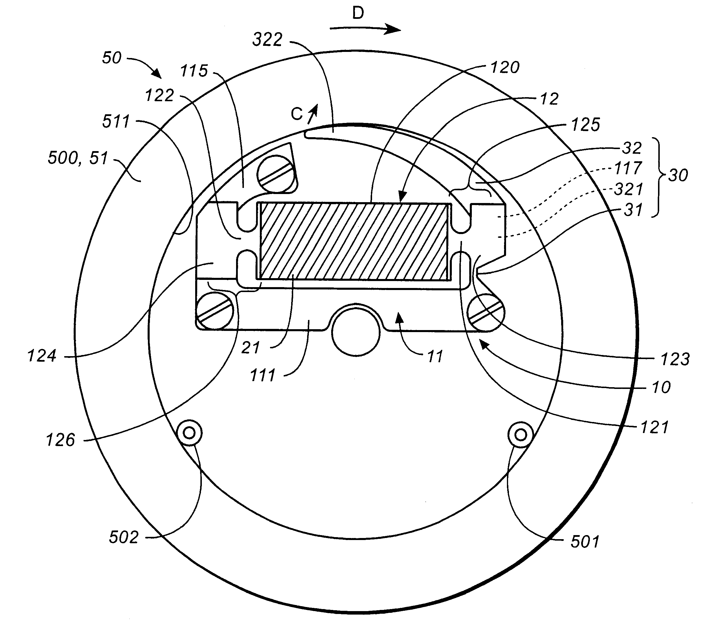
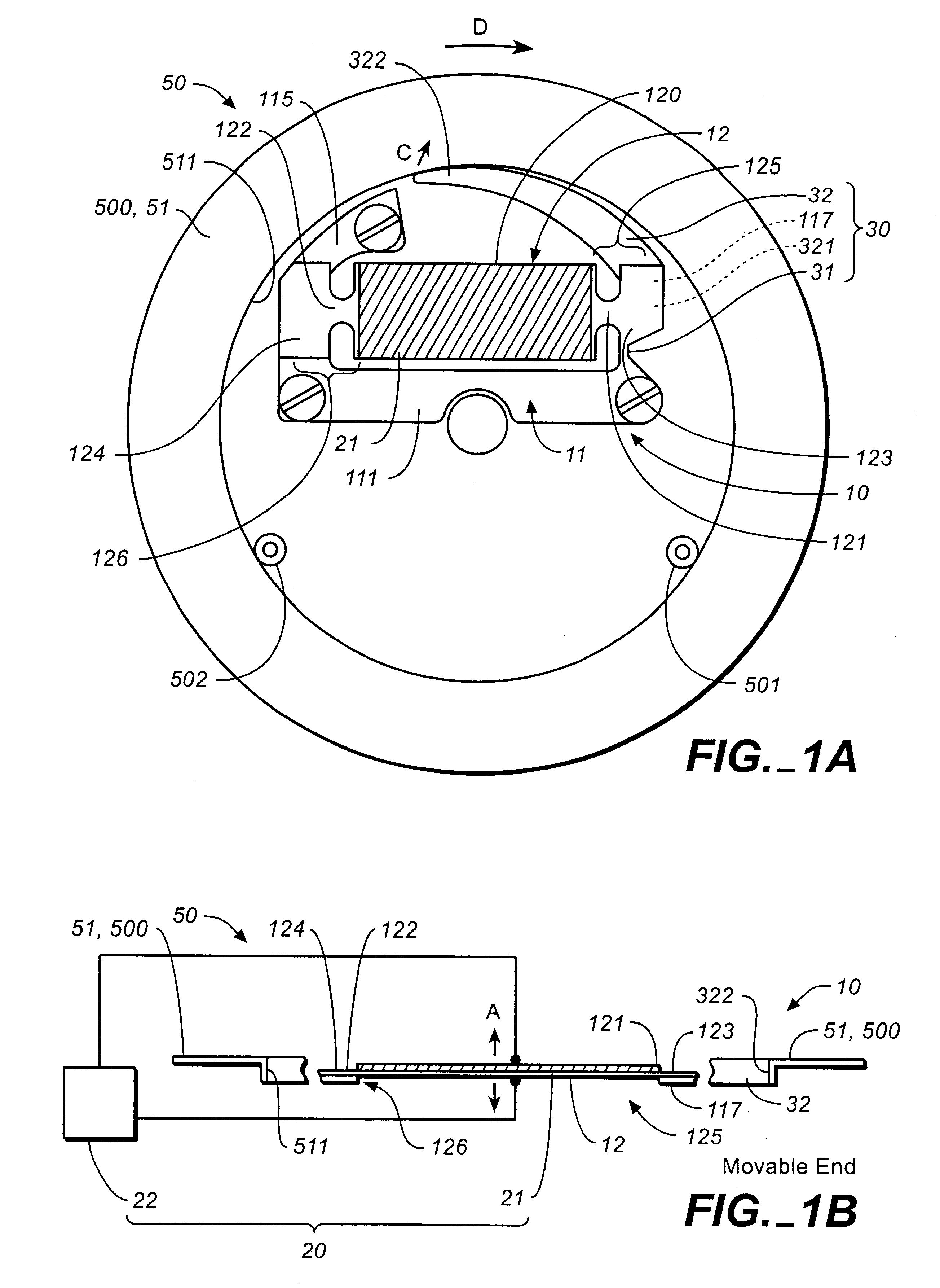
FIGS. 1(A) and 1(B) are a plan view and a sectional view of an actuator according to the present invention, and a sectional view of a principal part thereof, respectively.

An actuator 10 shown in these drawings is roughly composed of a metallic plate 11 having a thickness of about 0.5 mm secured and fixed by screws to a base (not shown), on which the actuator 10 is mounted, at three sections, a metallic vibrating plate 12 having a thickness of about 0.05 mm which is arranged two-dimensionally with respect to the plate 11 and whose both ends are supported by the plate 11 so as to enable bending vibrations in an out-of-plane direction, and an exciting means 20 for allowing the vibrating plate 12 to cause bending vibrations. In addition, in the actuator 10 of this embodiment, a vibration output system 30 is constructed which amplifies and outputs the bending vibrations of the vibrating plate 12 in the out-of-plane direction as vibrations in an in-plane direction utilizing the above-ment...

second embodiment

FIG. 3(A) and 3(B) are a plan view and a sectional view of a principal part of an actuator 10 according to the second embodiment of the present invention, respectively. Incidentally, since the basic configurations are common to the first embodiment and this embodiment and all of the embodiments described later, the corresponding portions are indicated by the same reference numerals and a description thereof will be omitted.

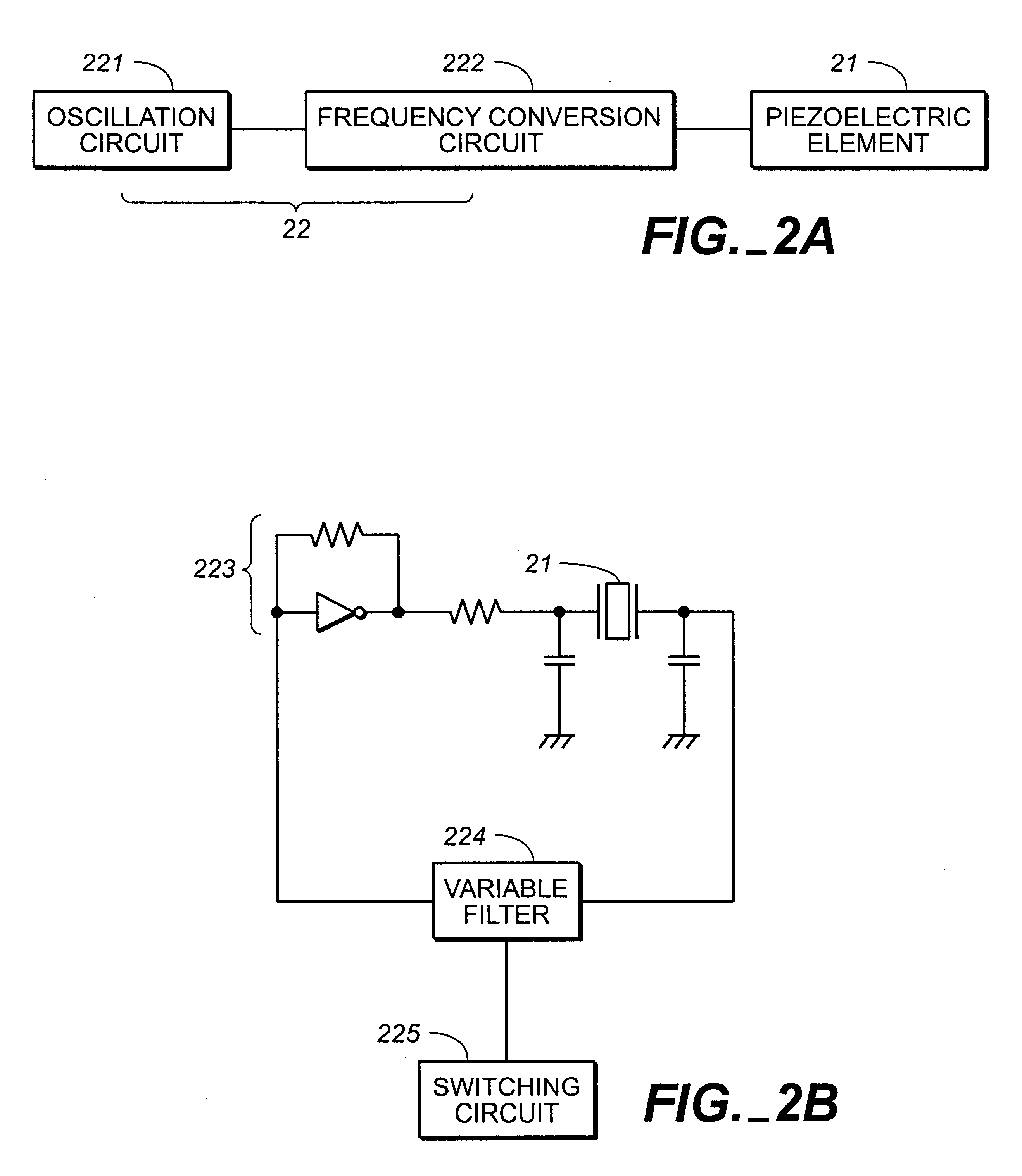
The actuator 10 shown in these drawings is also roughly composed of a plate 11 having a thickness of about 0.5 mm secured and fixed by screws to a base (not shown), on which the actuator 10 is mounted, at two sections, a vibrating plate 12 having a thickness of about 0.05 mm which is arranged two-dimensionally with respect to the plate 11 and whose both ends are supported by the plate 11 so as to enable bending vibrations in an out-of-plane direction, and an exciting means 20 (see FIG. 2(B)) including a piezoelectric element 21 for allowing the vibrating plate 12 ...

third embodiment

FIGS. 4(A) and 4(B) are plan view, and a sectional view of a principal part of an actuator 10 according to the third embodiment of the present invention, respectively.

The actuator 10 shown in these drawings is also roughly composed of two sheets of plates 11A and 11B each having a thickness of about 0.5 mm secured and fixed by screws to a base (not shown) on which the actuator 10 is mounted, a vibrating plate 12 having a thickness of about 0.05 mm which is arranged two-dimensionally with respect to the plates 11A and 11B and whose both ends are supported by each of the plates 11A and 11B so as to enable bending vibrations in an out-of-plane direction, and an exciting means 20 including a piezoelectric element 21 for allowing the vibrating plate 12 to cause bending vibrations, and a driving circuit 22. Since the basic configuration of the vibrating plate 12 is similar to that of the first embodiment, a description thereof will be omitted.

In the actuator 10 of this embodiment, first a...


PUM


Abstract

To provide an actuator which can achieve a reduction in size and weight of a device in which the actuator is mounted by amplifying and outputting displacement of a movable end of a vibrating plate as vibration in an in-plane direction, and to provide a timepiece and a notification device using the same, in an actuator (10), when a voltage is applied to a piezoelectric element (21) formed on a vibrating plate (12), the vibrating plate (12) generates bending vibrations in an out-of-plane direction, and one end portion (125) repeats displacement in an in-plane direction as a movable end. The displacement is transmitted to a lever (32) whose base end side (321) is connected to the end portion (125) of the vibrating plate (12) and an elastically deformable constricted portion (31), and a free end (322) of the lever (32) vibrates in the in-plane direction to drive a follower member (500).

Description

1. Technical FieldThe present invention relates to an actuator of a type using a vibrating plate, and to a timepiece and a notification device using the actuator. More particularly, the present invention relates to a structure for amplifying vibrations of the vibrating plate so as to output them as vibrations in an in-plane direction.2. Background ArtIn a calendar display mechanism for displaying a date, a day, and so forth in a wristwatch or the like, it is common for the rotational driving force from a step motor to be intermittently transmitted to a date indicator or the like through a watch-hand-driving train wheel so as to intermittently advance the date indicator or the like.In addition, a sound producer is mounted in a so-called portable electronic device, such as a pager and a mobile phone, and receipt of a message is notified to a user by producing an audible sound from the sound producer. Since it is not adequate for the device of this type to produce the audible sound in ...

Claims


Application Information

Patent Timeline
Patent Type & Authority Patents(United States)
IPC IPC(8): G04G13/02G04G13/00H01L41/09H02N2/10
CPCG04G13/02H02N2/103H02N2/002H02N2/0015
Inventor MIYAZAWA, OSAMU
Owner SEIKO EPSON CORP
Why Eureka
Try Eureka