
Surveying system with an inertial measuring device

a technology of inertial measurement and surveillance system, which is applied in the direction of distance measurement, instruments, movable markers, etc., can solve the problems of limited or impossible use of satellite-based position measuring units between houses

Inactive Publication Date: 2001-07-24
CARL-ZEISS-STIFTUNG TRADING AS CARL ZEISS
View PDF9 Cites 31 Cited by
  • Summary
  • Abstract
  • Description
  • Claims
  • Application Information

AI Technical Summary

Benefits of technology

The well-established surveying systems can be further improved if the sighting device is the measuring telescope of a theodolite or a tachymeter and, for example, the target point carrier includes a reflector.

Problems solved by technology

Thus the use of the satellite-based position measuring unit is limited or impossible between houses, in surveying from corners of houses, under trees, under bridges, in ravines, and in buildings.

Method used


Image

  • Surveying system with an inertial measuring device
  • Surveying system with an inertial measuring device

Examples


Embodiment Construction

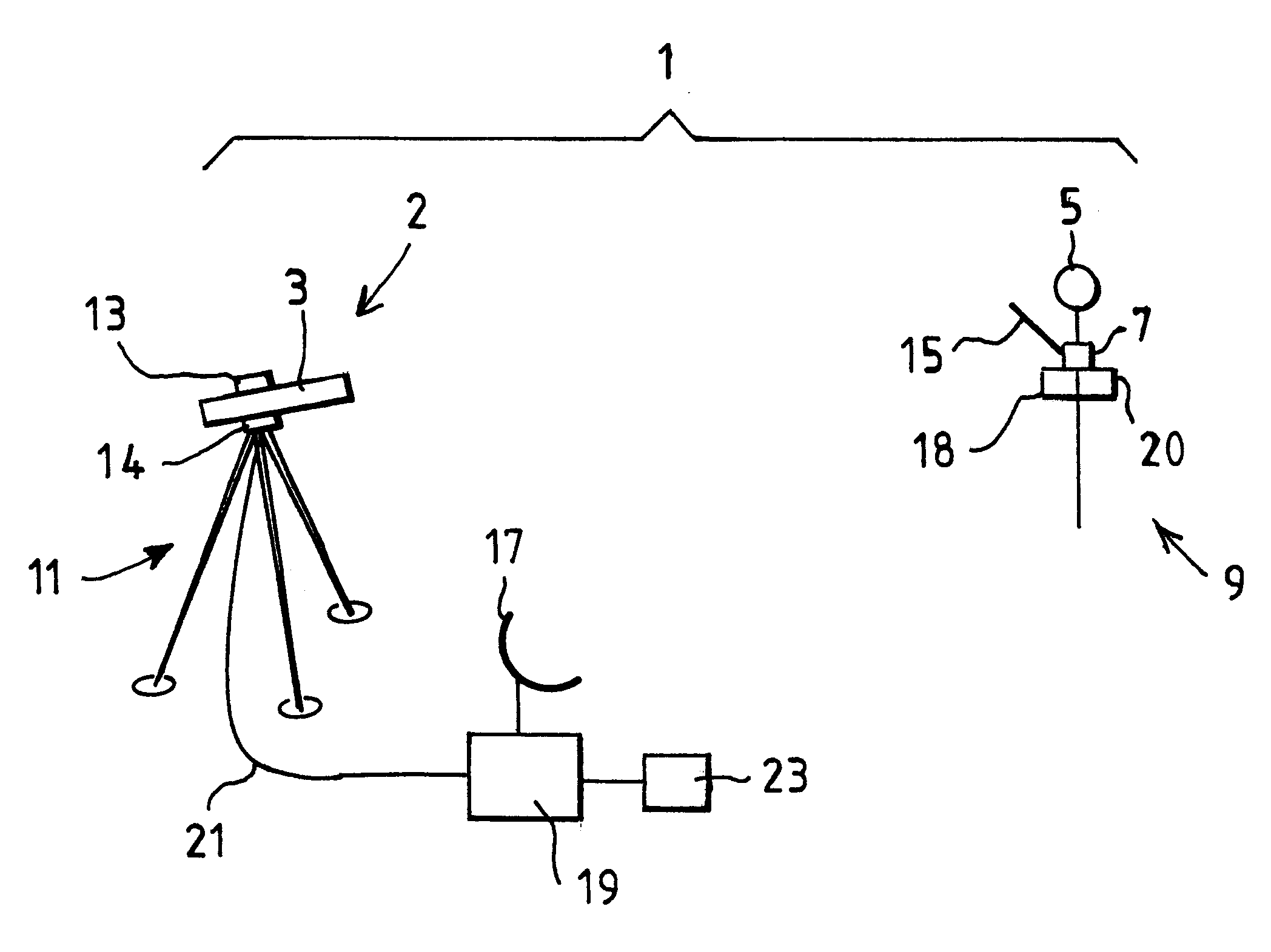
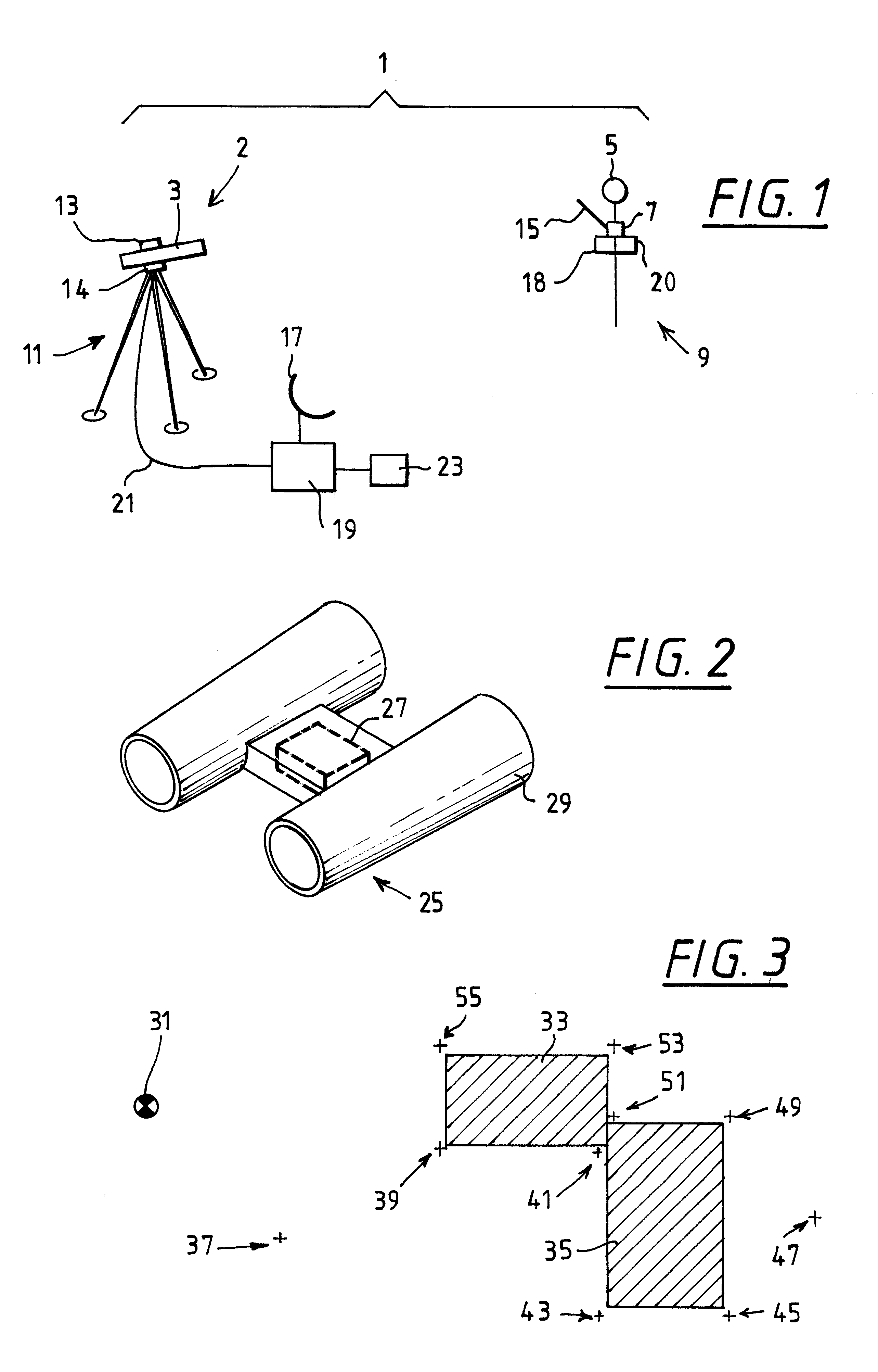
In FIG. 1, a surveying system 1 according to the invention is shown schematically. The surveying system 1 includes a sighting device 2 with a telescope 3, with which a target point 5 is sighted, in order to be able to measure the angular position and the distance of the target point 5 in relation to the sighting device 2. The target point 5, constructed as a reflector, is arranged together with an inertial measuring device 7 on a rod-shaped target point carrier 9.

The measuring telescope 3 is arranged to be rotatable around a vertical axis, and pivotable around a horizontal axis, gimbal-mounted on a stand 11, and includes a distance measuring device 13 which measures the distance to the target point 5, so that the position of the target point can be determined when the position of the measuring telescope is known.

Measurement values supplied from the inertial measuring device 7 when the target point 5 is displaced are transmitted to an evaluation unit 19 by means of a transmitting ant...


PUM


Abstract

A surveying system has a sighting device and a position measuring unit. The position measuring unit includes an inertial measuring device.

Description

1. Field of the InventionThe invention relates to a surveying system and, more particularly, to a surveying system having a sighting device and a position measuring unit, and also to surveying process using such a surveying system.2. Description of Relevant ArtA surveying system of the given category is known, for example, from European Patent EP 0 481 307 A2. This document discloses a tachymeter with a GPS (Global Positioning System) position measuring unit; that is, a satellite-based position measuring unit, wherein both the sighting device, i.e., the tachymeter proper, and also the reflector rod to be sighted with the tachymeter, are equipped with a satellite-based position measuring device.However, the satellite-based position measuring unit requires free lines of sight to at least four satellites. Thus the use of the satellite-based position measuring unit is limited or impossible between houses, in surveying from corners of houses, under trees, under bridges, in ravines, and i...

Claims


Application Information

Patent Timeline
IPC IPC(8): G01C15/00G01C21/10G01C21/16G01C5/00G01C3/00G01C15/06G01C19/02
CPCG01C21/16G01C15/00
Inventor HUEP, WOLFGANGMICHELBACHER, ERNST
Owner CARL-ZEISS-STIFTUNG TRADING AS CARL ZEISS
Learn More