Advanced tray support system using orthogonal grillage

a technology of support system and tray, which is applied in the direction of machine/engine, combustion air/fuel air treatment, separation process, etc., can solve the problems of large amount of materials, large physical size of support beam, and high cost of support beam, so as to facilitate the free movement of process gas flow, improve process utility of trays, and reduce material costs of trays

Inactive Publication Date: 2001-07-31
STONE & WEBSTER PROCESS TECH
View PDF19 Cites 30 Cited by
  • Summary
  • Abstract
  • Description
  • Claims
  • Application Information

AI Technical Summary

Benefits of technology

It is therefore an object of the present invention to provide new and useful improvements to the support of trays. The use of the trays of the present invention are generally self supporting, thereby enabling a reduction in the number of support beams required for a given column diameter as compared to the trays of the prior known art, or in some cases the complete elimination of such support beams.
It is a further object of the present invention to provide trays which are resistant to explosive uplift forces which are common in some process applications.
It is another object of the present invention to improve the process utility of the trays by facilitating the free movement of the process gas flow between the various sections of the columns.
It is still a further object of the present invention to provide economic advantages over the prior known art of tray support systems. Elimination and / or reduction in the number of support beams, beam seats, clips and bolting reduces the material costs of the trays, as well as the labor costs concomitant with their installation within new columns.

Problems solved by technology

Although the use of support beams to support trays provides sufficient support to the trays to sustain a given deflection criterion, the use of support beams suffers from both technical and economic disadvantages.
Economically, support beams are physically large, constitute large quantities of materials, are expensive and are difficult to install, especially in revamping an existing column in the field.
Technically, support beams typically have the effect of becoming partitions within the columns, thus inhibiting the free movement of process gases through the column and thereby potentially causing deleterious effects upon the process itself.
Still further, the use of support beams reduces the active area of the tray because the horizontal flange of the beam blocks the part of the tray which could otherwise be active for process reasons.

Method used


Image

  • Advanced tray support system using orthogonal grillage
  • Advanced tray support system using orthogonal grillage
  • Advanced tray support system using orthogonal grillage

Examples


Embodiment Construction

As used throughout the present specification, the terms "process", "tray", "stiffener", etc. shall be as here-to-fore defined.

As used throughout the present specification the term "stiffener" expressly excludes any sort of non-integral stiffener, including but not necessarily limited to support beams.

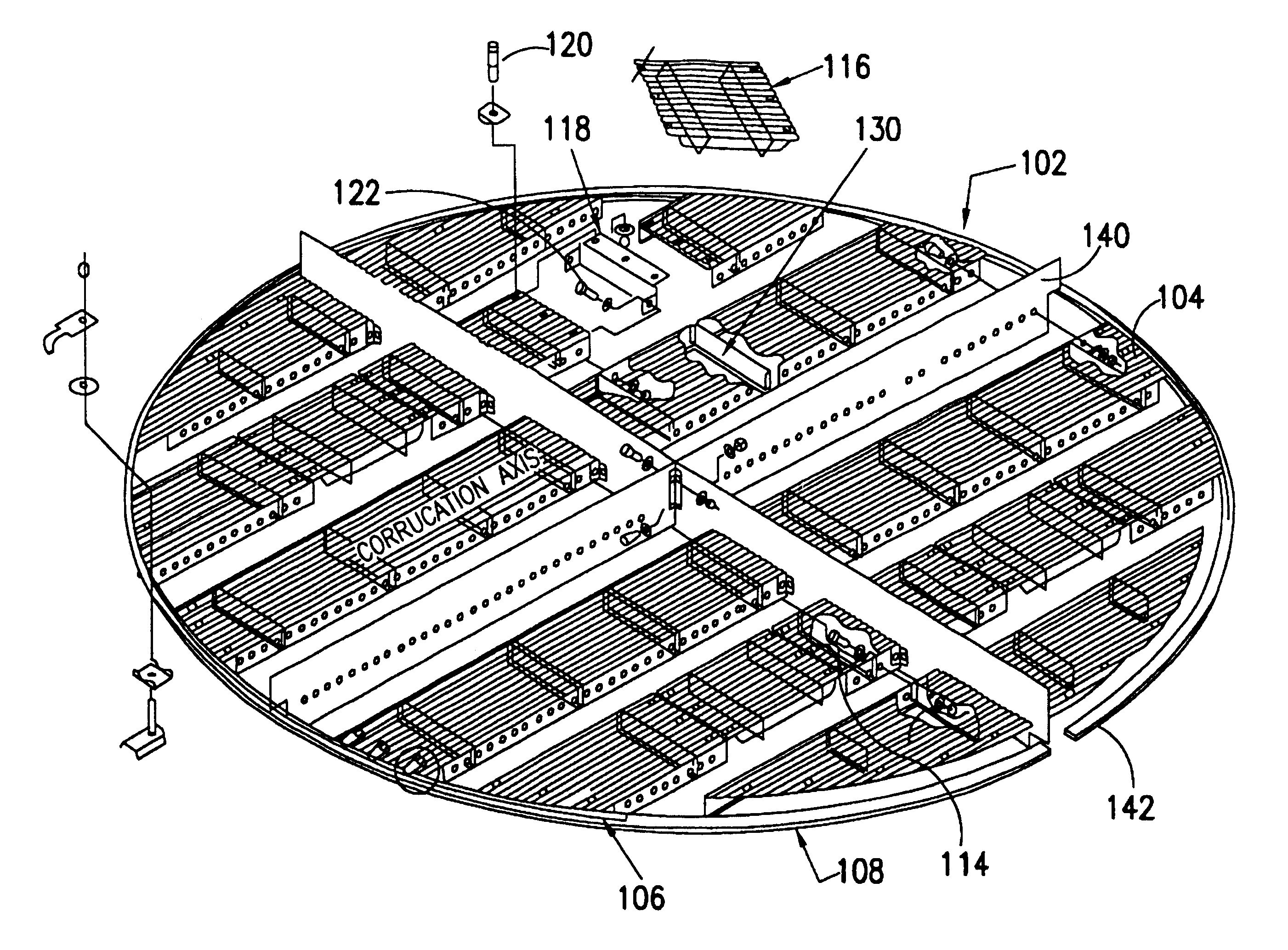
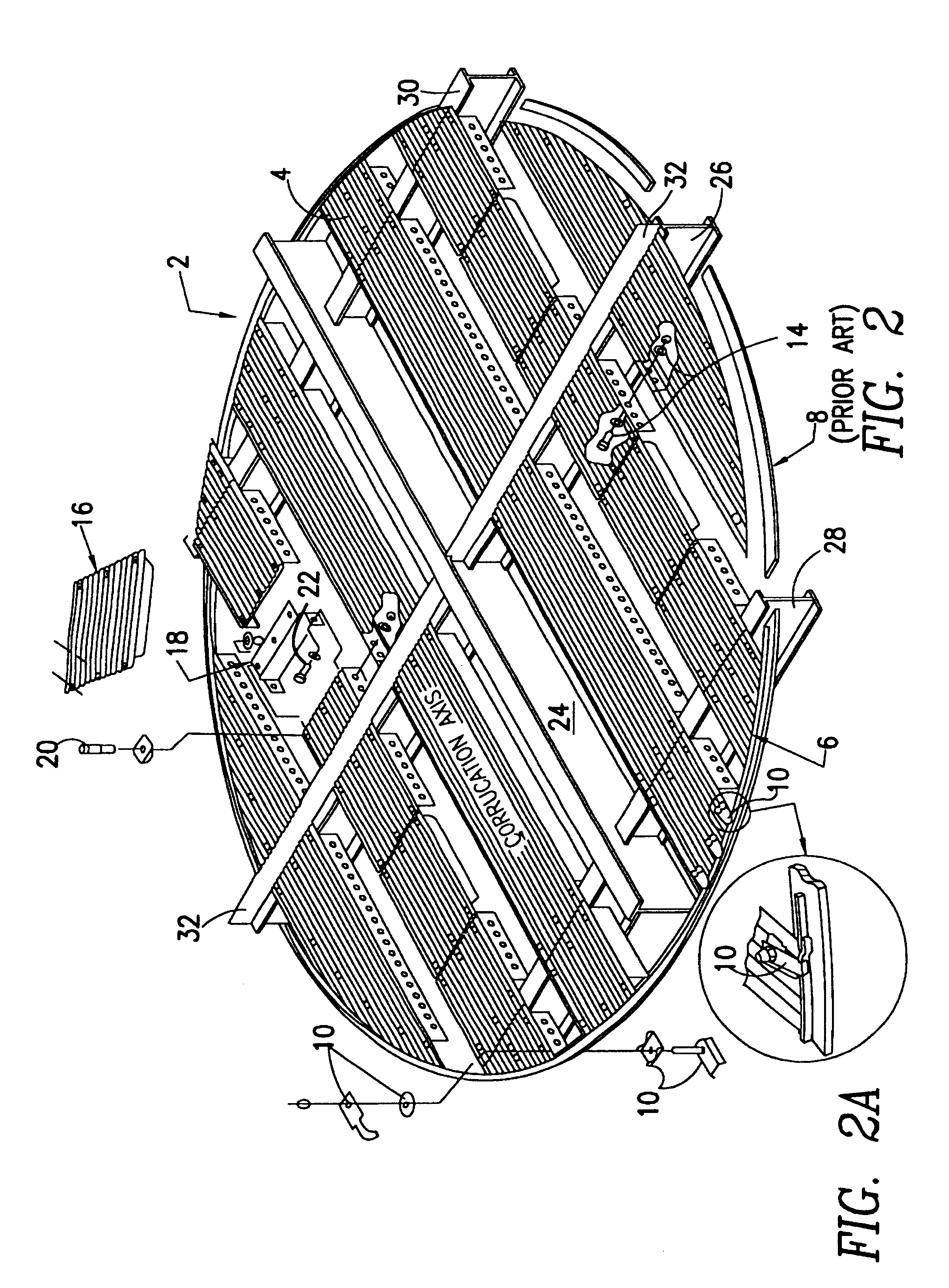
Referring to FIG. 2 there is shown a process tray sold under the trademark RIPPLE TRAY 2 of the prior known art. A process tray sold under the trademark RIPPLE TRAY 2 comprises several corrugated tray panels 4 which are attached at their respective outer ends to a circular shaped seal ring 6, such as by clamping means 10 as best seen in FIG. 2A. The seal ring 6 and the a process tray sold under the trademark RIPPLE TRAY are supported and attached to the column interior wall by tray support ring 8, such as by clamping means 10. The tray panels 4 may further be attached to one another via bolting means 14.

Typically one of the panels shall also include a manway panel 16. The manway panel i...


PUM


Abstract

The present invention relates to the use of orthogonal tray stiffeners in supporting tray panels for process tray.

Description

The present invention relates to a method and apparatus for supporting process trays. More particularly, the present invention relates to a method and apparatus for providing a tray which can support heavy loadings with low degree of deflection and which requires fewer or no non-integral support beams.As used throughout this document, the following definitions shall apply:"process" shall be taken to mean, but not necessarily limited to Distillation, Flashing, Rectification, Absorption, Stripping, Evaporation, Humidification, Dehumidification, Dephlegmation, Spray Drying, Heat Transfer or any combination thereof."Tray", shall be taken to be any plate type contact device used in liquid-gas or liquid-liquid mass and / or heat transfer operations. Mass and / or heat transfer process equipment using trays is based on a combination of operating principles essentially defined by three categories:1. Mode of flow of streams: Counter-current; Co-current; and Cross-flow.2. Gross mechanism of trans...

Claims


Application Information

Patent Timeline
Patent Type & Authority Patents(United States)
IPC IPC(8): B01D3/14B01D3/32
CPCB01D3/326B01D3/324
Inventor STIPPICK, JOHN
Owner STONE & WEBSTER PROCESS TECH
Why Eureka
Try Eureka