Method and circuit for driving piezoelectric transformer

a piezoelectric transformer and circuit technology, applied in the direction of dc-ac conversion without reversal, device details, piezoelectric/electrostrictive device details, etc., can solve the problem that the frequency control cannot be performed based on only a signal from an oscillating state of piezoelectric elements, and achieve high load dependency, prevent the breakage of the piezoelectric transformer, and high efficiency

Inactive Publication Date: 2001-07-31
NEC CORP
View PDF9 Cites 36 Cited by
  • Summary
  • Abstract
  • Description
  • Claims
  • Application Information

AI Technical Summary

Benefits of technology

Therefore, it is an object of the present invention to provide a method and circuit for driving a piezoelectric transformer which is capable of preventing the breaking down of the piezoelectric transformer caused by excessive oscillation on activation thereof and simultaneously of achieving high efficiency in the method and circuit for driving the piezoelectric transformer having a feature of high load dependency and which is loaded with a cold cathode tube having a high variation in impedance. Other objects and advantages of the present invention will become apparent from the entire disclosure including the following description.
According to an aspect of the present invention, the present invention is char

Problems solved by technology

However, frequency control can not be performed based upon only a signal from an oscillating state of piezoelectri

Method used


Image

  • Method and circuit for driving piezoelectric transformer
  • Method and circuit for driving piezoelectric transformer
  • Method and circuit for driving piezoelectric transformer

Examples


embodiments

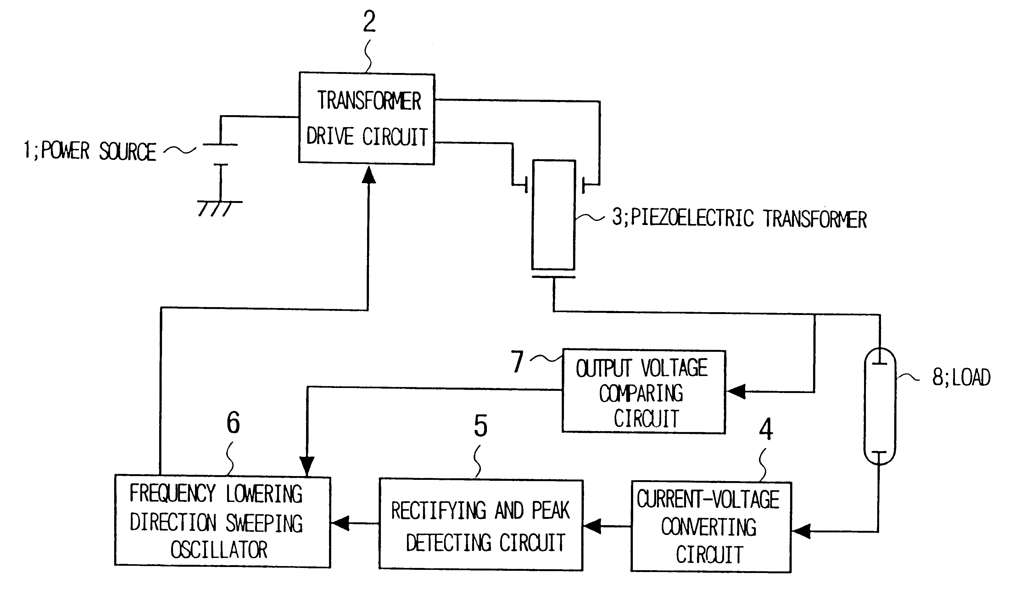
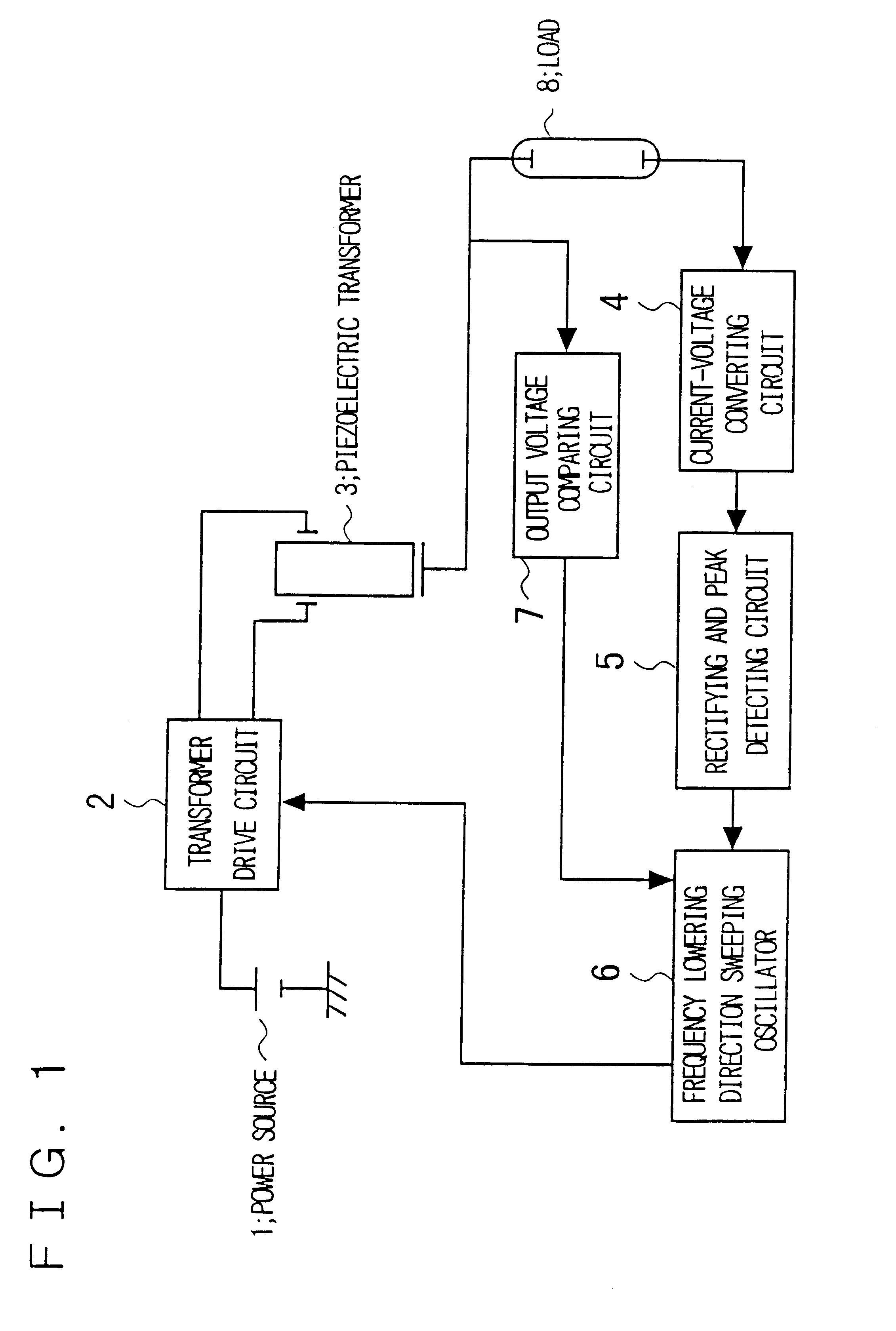
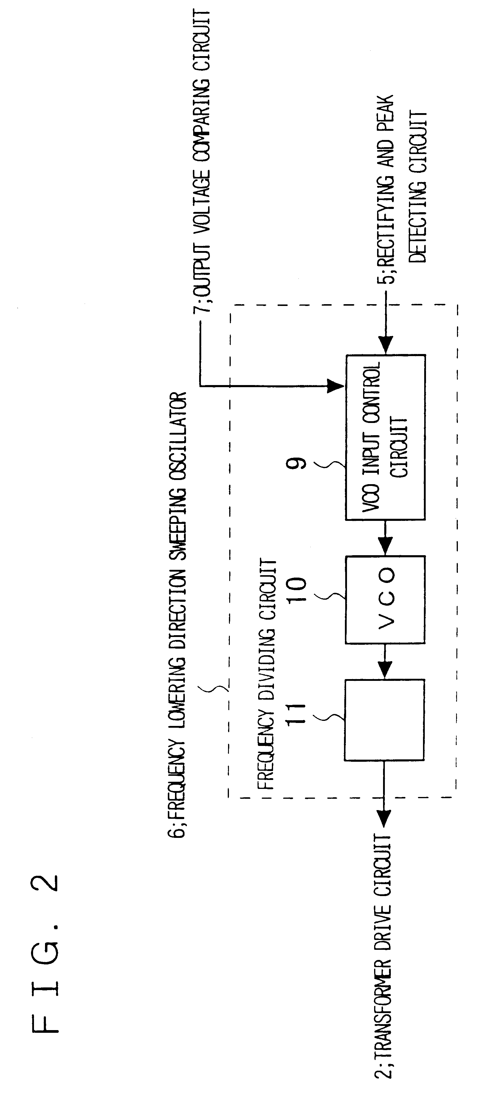
FIG. 1 is a block diagram showing the configuration of one embodiment of the present invention. The piezoelectric transformer has characteristics that its resonating frequency and its step up ratio change depending upon the load impedance as shown in FIG. 10. In a drive circuit in one embodiment of the present invention, the piezoelectric transformer inverter comprises a piezoelectric transformer 3 which converts an ac voltage which is input from its primary side and outputs the converted voltage at its secondary side by using its piezoelectric effect, a transformer drive circuit 2 which is connected to input electrodes of the piezoelectric transformer for converting the voltage of the power source into a necessary input voltage of the piezoelectric transformer so that the piezoelectric transformer 3 provides a predetermined output responsive to a control signal from a frequency lowering direction sweeping oscillator 6, a load 8 which is connected to an output electrode of the piezo...


PUM


Abstract

To provide a piezoelectric transformer drive method and a drive circuit which is capable of preventing breakdown of the piezoelectric transformer due to excessive oscillation on its activation and of obtaining a high efficiency. Controller controlling the load power to a constant value is provided. The controller is controlled in such a manner that the driving of the piezoelectric transformer is initiated at a frequency higher than the resonating frequency on its activation and thereafter the drive frequency is gradually lowered without passing through the resonating frequency of the piezoelectric transfer on its activation.

Description

The present invention relates to a piezoelectric transformer drive circuit and in particular to a drive method and circuit which is preferably used for driving of a piezoelectric transformer which is connected with a cold cathode tube having a high variation in impedance as a load.A prior art activating device in which the frequency of a voltage applied to a piezoelectric element is preset to a frequency which is higher than an intended drive frequency and is higher than the resonating frequency and is lower than the harmonics of the resonating frequency, and is gradually lowered is disclosed in, for example, Japanese patent Kokai publication JP-A-3-22873. This is a driving device of an ultrasonic motor for preventing the occurrence of uncomfortable noise on activation of the ultrasonic motor. This prior art device will be described with reference to FIG. 16.A plurality of electrostrictive elements of polarized piezoelectric material are disposed on the surface of an ultrasonic moto...

Claims


Application Information

Patent Timeline
IPC IPC(8): H01L41/00H01L41/04H05B41/28H05B41/282H02M7/48
CPCH05B41/2822H01L41/044H10N30/804H05B41/24
Inventor YAMAGUCHI, SHUUJIFURUHASHI, NAOKI
Owner NEC CORP
Why Eureka
Try Eureka