Door mechanism for automobile air conditioner

a door mechanism and air conditioner technology, applied in vehicle parts, vehicle heating/cooling devices, vehicle cleaning, etc., can solve the problems of complicated and high-cost construction, further limited small vehicle cabin space, and difficulty in controlling the distribution of cooled air and warmed air

Inactive Publication Date: 2001-08-07
CALSONIC KANSEI CORP
View PDF11 Cites 33 Cited by
  • Summary
  • Abstract
  • Description
  • Claims
  • Application Information

AI Technical Summary

Problems solved by technology

Thus, when such device is mounted in a small car, the smaller vehicle cabin space is further limited, which is undesirable.
However, in the unit having the above-mentioned construction, the reduction in size of the door 5 tends to cause a difficulty with which distribution of cooled air and warmed air is controlled.
However, in this case, the addition of such auxiliary door causes a complicated and highly costing construction, which is of course undesirable.
However, a door mechanism possessed by the above-mentioned vertically sliding type tends to show weak points in operability and sealing performance.
However, if the clearance is too small, the sliding resistance become increased causing non-smoothed movement of the door 9.
While, if, for achieving a smoothed movement of the door, a larger clearance is provided between them, the undesired air leakage tends to occur.
In a door mechanism of a slide door type wherein, like the door 9 described in the above-mentioned publication, a plate type door is slid, it is difficult to achieve a satisfied sealing.
In view of this, it is difficult to keep an adequate sealing for a long time.
That is, even when the door comes to the terminal position that is, close position, undesired air leakage tends to occur in relatively early time, and thus, if such slide type door is used as the mix door, the temperature control performance is inevitably lowered due to the poor sealing.
When the door is applied with a certain pressure, noises caused by the play tend to be produced which are transmitted to the vehicle cabin to make passengers uncomfortable.
Thus, bulky structure of the device makes installation in a motor vehicle, particularly in a smaller motor vehicle difficult.
That is, in the devices, it is necessary to prepare a structure by which the passage is defined as well as separate parts, which causes an increase in cost and a need for a certain space for mounting therein the separate parts.
Thus, the door proper never produces play even when applied with wind pressure.
Even if the sliding mechanism employs the gears, undesired gear slippage never occurs under operation of the gears and thus smoothed operation is achieved.
Furthermore, since the cam grooves help the sealing member to be pressed against the contacting member through the door proper, lowering in sealing performance is suppressed for a long time and thus sealing performance is increased.
Furthermore, reduction in air flow resistance is expected.

Method used


Image

  • Door mechanism for automobile air conditioner
  • Door mechanism for automobile air conditioner
  • Door mechanism for automobile air conditioner

Examples


embodiment-1

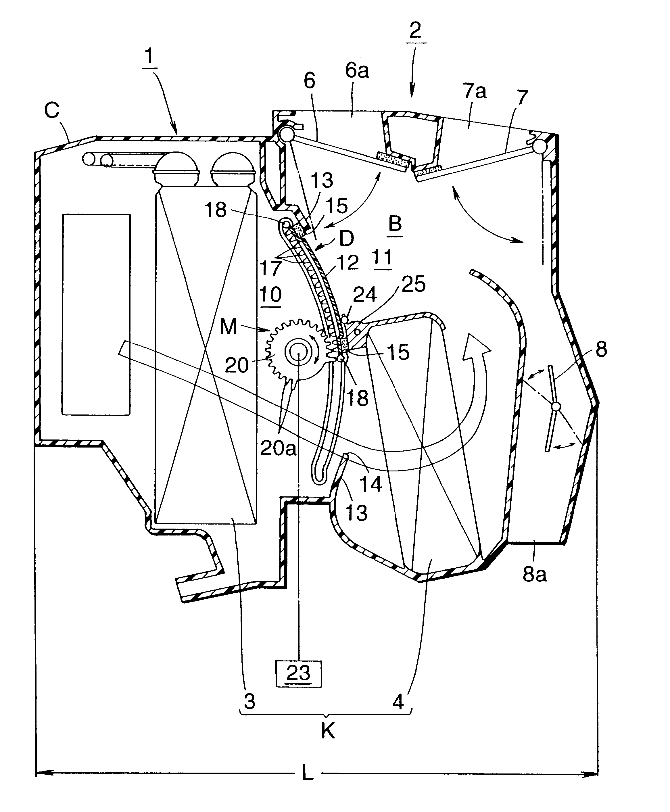
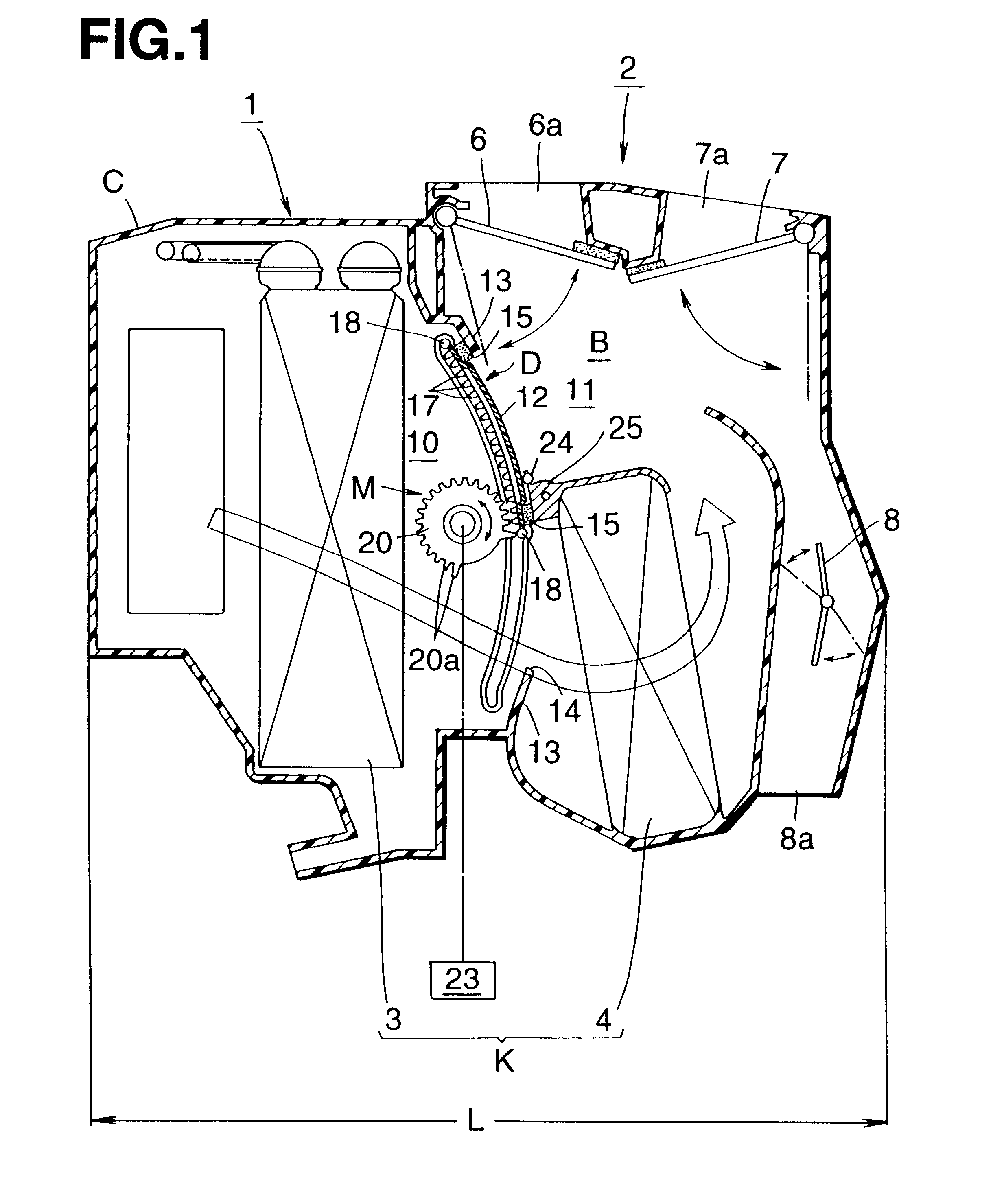
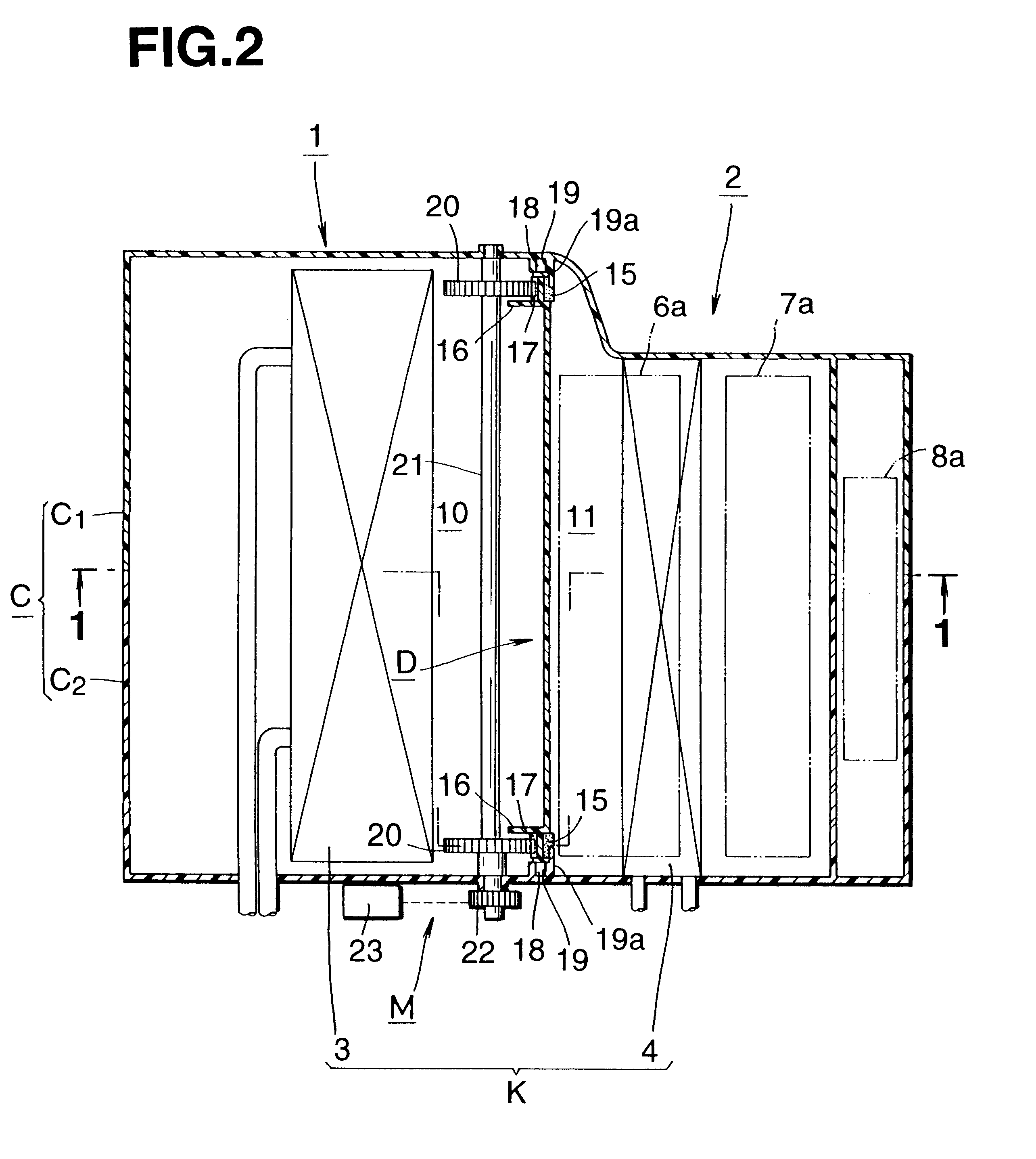
FIG. 1 is a drawing showing an automotive air conditioning device which is an embodiment-1 of the present invention, which is a sectional view taken along the line 1--1 of FIG. 2. FIG. 2 is a plan view of FIG. 1, FIG. 3 is a horizontally sectional view of a door mechanism, FIG. 4 is a partially cut perspective view of a door, FIG. 5 is an end view taken along the line 5--5 of FIG. 3, FIG. 6 is an enlarged illustration showing an essential portion of the door, FIG. 7 is an illustration showing a cam groove portion, and FIG. 8 is an illustration of a supporting roller, which is a sectional view taken along the line 8--8 of FIG. 7. It is to be noted that parts similar and corresponding to those of FIGS. 18 and 19 are denoted by the same reference numerals as those of FIGS. 18 and 19.

As is shown in FIG. 1, a door mechanism of an automotive air conditioning device of the embodiment-i is applied to a mix door.

As is shown in FIG. 1, in the automotive air conditioning device, there is used ...

embodiment-2

FIG. 9 is a drawing showing essential portions of an automotive air conditioning device which is embodiment-2 of the present invention. Members and parts similar to those of FIGS. 1 to 8 are denoted by the same numerals.

As is shown in FIG. 9, a door mechanism of an automotive air conditioning device of the embodiment-2 is applied to an intake door.

An intake unit 30 associated with the embodiment-2 is a device which selectively intakes vehicle outside air (outside air) and vehicle inside air (inside air) and conditions the mixed air by flowing the same in an air conditioning device before blowing into the vehicle cabin. Like in the case of the above-embodiment, it is desirable to reduce a height "H" of an intake door D installed in the unit. In fact, flatten-shape of the intake door is preferable.

In the intake unit 30, air intake from the upstream air passage 10 is made by running a fan 31 via a motor 32. The upstream air passage 10 has an outside air intake passage 10a and an inside...

embodiment-3

As is shown in FIG. 11, an automotive air conditioning device of this embodiment is connected to an intake unit 160 which, after introducing the outside or inside air, leads the air to a downstream portion. The intake unit 160 is formed with both an outside air intake port 161 for introducing the outside air and an inside air intake port 162 for introducing the inside air for the air circulation. Selection of the ports 161 and 162 is made by an intake door 163. In order to forcibly transfer the air from the intake port 161, the intake port 162 or both of them to the downstream portion, there is arranged a fan which is driven by a motor 164 installed in the intake unit.

The automotive air conditioning device 150 comprises a case C which is integral with a frame of the cooler unit 101 and a frame of the heater unit 102. In an upstream part of an air passage of the case C, there is arranged an evaporator 103 which is connected to a refrigerating cycle (not shown). The introduced air is ...


PUM


Abstract

A mix door D, which is arranged in a limited space defined between an upstream air passage 10 in which an evaporator 3 is installed and a downstream air passage 11 in which a heater core 4 is installed, is of a sliding type. By guiding a door proper 12 by using a cam groove, a seal member 15 bonded to the door proper 12 is pressed against a contacting member 13 only when the door proper 12 assumes its close position. Smoothed operation of the door proper 12 is achieved with a compact construction of a unit, and sealing and temperature controlling performance is increased.

Description

The present invention relates to a door mechanism of an automotive air conditioning device, which can slide in a limited space to control air flow.TECHNICAL BACKGROUNDIn general, an automotive air conditioning device comprises an intake unit for introducing outside and inside air, a cooler unit for cooling the introduced air and a heat for heating the introduced air, these three units being combined in series and installed in a limited space of a vehicle cabin, such as a space defined below an instrument panel.However, due to the in-line connection of the three units, the automotive air conditioning device is compelled to have an enlarged size. Thus, when such device is mounted in a small car, the smaller vehicle cabin space is further limited, which is undesirable.In view of the above, as is shown in FIG. 18, there has been proposed a device in which a cooler unit 1 and a heater unit 2 are positioned close to each other and aligned along a fore-and-aft direction of the vehicle ther...

Claims


Application Information

Patent Timeline
Patent Type & Authority Patents(United States)
IPC IPC(8): B60H1/00
CPCB60H1/00857B60H1/00692
Inventor TSURUSHIMA, AKIHIROIJICHI, TAKUMIKUROKAWA, KATSUHIROUCHIDA, TOSHIYAONDA, MASAHARU
Owner CALSONIC KANSEI CORP
Why Eureka
Try Eureka