Acoustic igniter and ignition method for propellant liquid rocket engine

a technology of propellant liquid and igniter, which is applied in the direction of machines/engines, marine propulsion, vessel construction, etc., can solve the problems of poor combustion stability, low reliability, and low efficiency of acoustic igniters of the past, so as to achieve stable and reliable ignition, reduce thermal losses, and increase the effect of intensity

Inactive Publication Date: 2001-08-14
SN DETUDE & DE CONSTR DE MOTEURS DAVIATION S N E C M A
View PDF5 Cites 14 Cited by
  • Summary
  • Abstract
  • Description
  • Claims
  • Application Information

AI Technical Summary

Benefits of technology

The present invention seeks to remedy the above-mentioned drawbacks, and in particular to provide an acoustic igniter presenting oscillations of greater intensity due to shock waves, smaller thermal losses that are from the acoustic resonator, and in general, operation that is optimized so as to be more stable and more reliable than existing devices, thus contributing in particular to reducing the time required for ignition.

Problems solved by technology

Prior art acoustic igniters are not optimized with respect to operation or with respect to geometry.
Combustion stability is not very good, and given the low initial temperature of the gaseous component, ignition does not take place with the desirable degree of reliability.
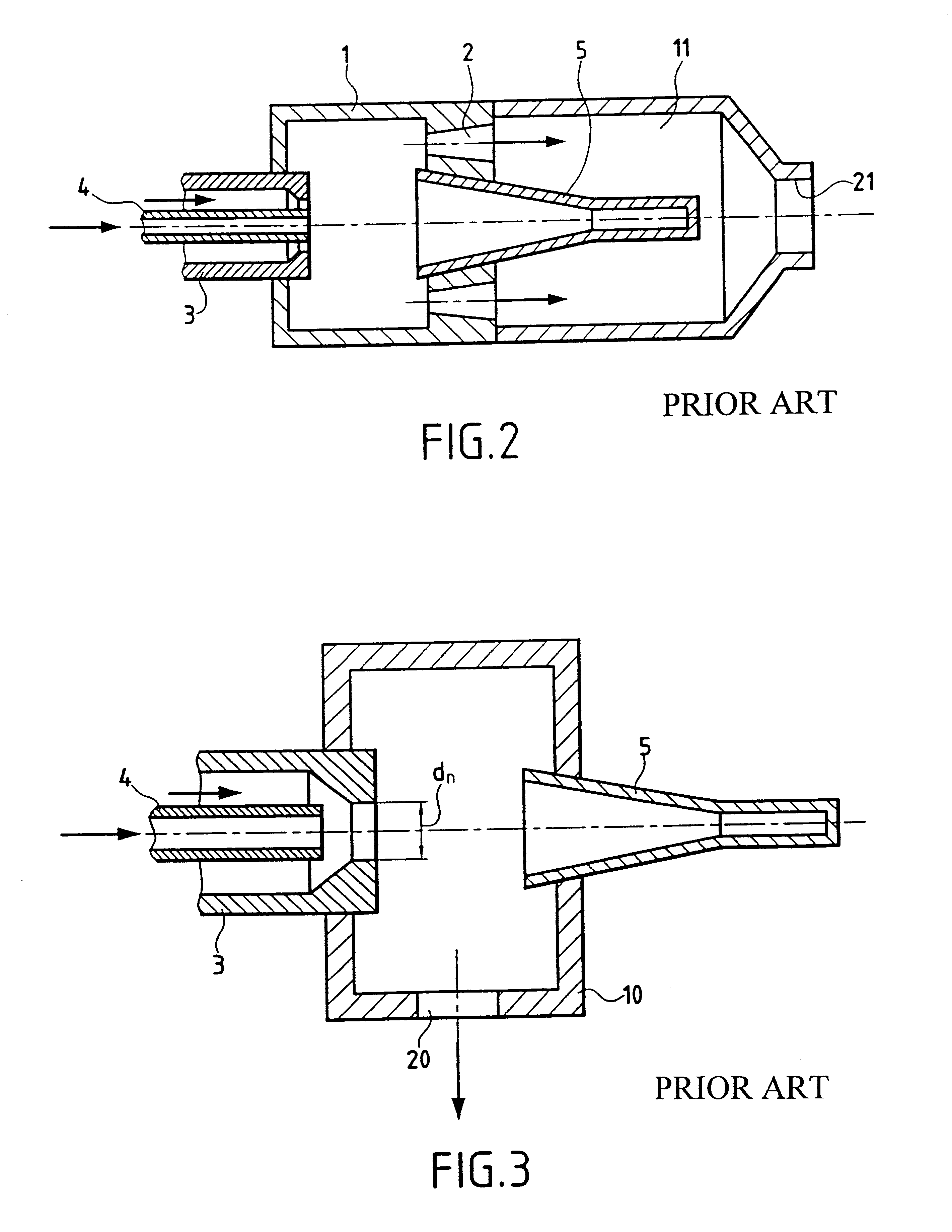
Nevertheless, the acoustic igniter of FIG. 3 is still not sufficiently reliable, and in particular it does not enable the maximum length of time required for ignition to be reduced.

Method used


Image

  • Acoustic igniter and ignition method for propellant liquid rocket engine
  • Acoustic igniter and ignition method for propellant liquid rocket engine
  • Acoustic igniter and ignition method for propellant liquid rocket engine

Examples


Embodiment Construction

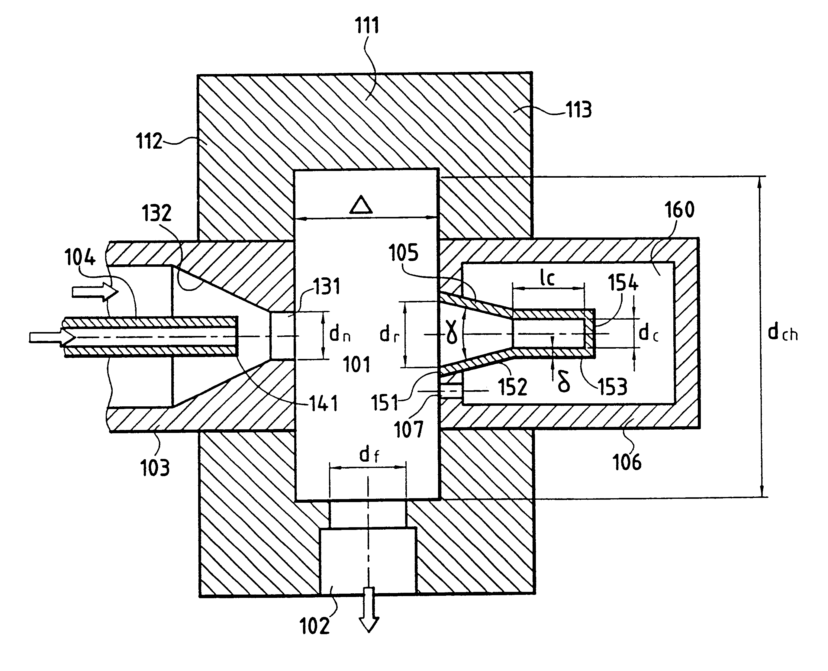
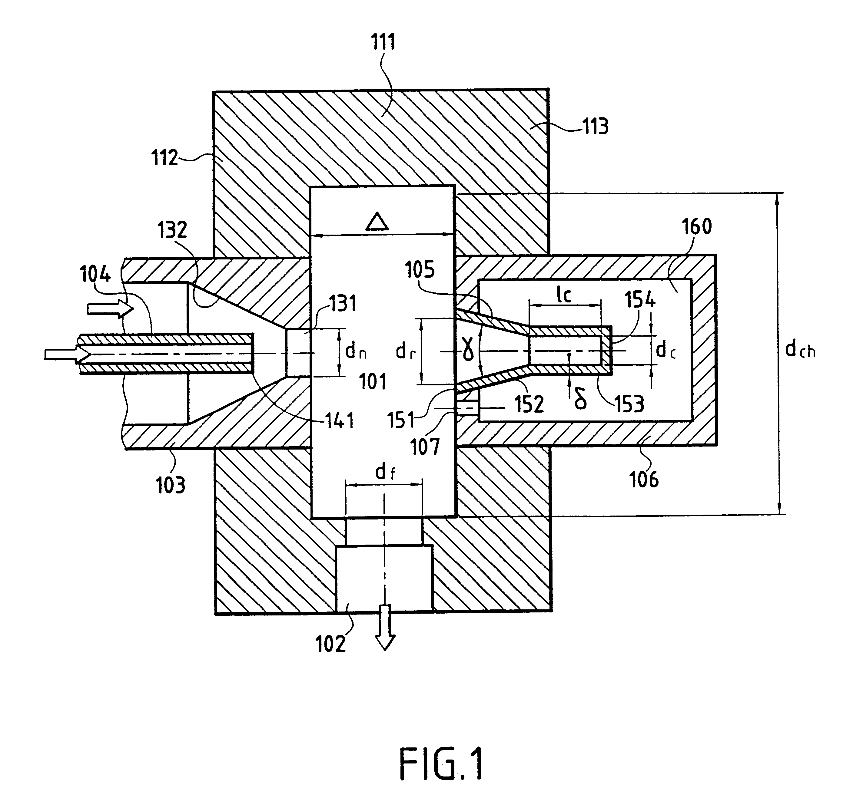
Reference is made to FIG. 1 which shows an example of an acoustic igniter of the invention. This acoustic igniter comprises a cylindrical precombustion chamber 1 having a cylindrical wall 111 and essentially plane end walls 112 and 113. One or more outlet orifices 102 each of minimum diameter d.sub.f are provided through the cylindrical wall 111. A propellent injection nozzle 103 opens out into the precombustion chamber 101 through the wall 112 via an orifice 113 of minimum diameter d.sub.n. A fuel injection tube 104 is disposed inside the nozzle 103 on its axis and having a downstream end 141 situated in the converging portion 132 of the nozzle 103. An acoustic resonator 105 defines a cavity that opens out into the chamber 101 through the wall 113 via an opening 151 of diameter d.sub.r.

The fact that the end of the injector-forming tube 104 terminates inside the nozzle 103, in the converging portion 132 thereof, and is set back from the orifice 131, makes it possible to achieve bett...


PUM

PropertyMeasurementUnit
convergence angleaaaaaaaaaa
pressureaaaaaaaaaa
temperatureaaaaaaaaaa

Abstract

The invention concerns an acoustic igniter for igniting a mixture of rocket fuels in a liquid propellant rocket engine combustion chamber comprising a cylindrical precombustion chamber (101) including a cylindrical wall (111) and first and second end walls (112, 113), a rocket fuel injection nozzle (103) emerging into the precombustion chamber (101) through the first end wall (112) via an orifice of diameter dn, a rocket fuel injector (104) arranged inside said nozzle (103) along the axis thereof, at least an outlet orifice (102) of minimum diameter df provided in the cylindrical wall (111), an acoustic resonator (105) defining a cavity opening into the precombustion chamber (101) opposite the nozzle (103), through the second end wall (113), via an orifice (151) of diameter dr. The acoustic resonator (105) is enclosed by a housing (106) which defines around the acoustic resonator (105) a closed auxiliary chamber (160) which communicates only with the precombustion chamber (101) by at least one conduit (107).

Description

The present invention relates to an acoustic igniter and to a method of igniting a propellent mixture in the combustion chamber of a liquid propellent rocket engine.PRIOR ARTVarious types of acoustic igniter are already known for use in space to ignite propellent mixtures fed to the combustion chamber of a liquid propellent rocket engine.Thus, patent document SU-A-1 255 818 has already described an example of an acoustic igniter as shown in FIG. 2. In such an acoustic igniter, a cylindrical precombustion chamber 1 has an injection nozzle 3 on one of its main faces with an injector 4 placed inside the nozzle for feeding fuel, with the injector 4 lying on the axis of the injection nozzle 3. A hollow acoustic resonator 5 is placed across the second main face of the precombustion chamber 1 facing the injection nozzle 3. The acoustic resonator 5 includes a frustoconical first portion that converges from the inlet opening thereof, and a cylindrical second portion that defines a cavity whi...

Claims


Application Information

Patent Timeline
Patent Type & Authority Patents(United States)
IPC IPC(8): F02K9/00F02K9/95
CPCF02K9/95
Inventor KESSAEV, KHOZEZINOVIEV, VASSILIDEMTCHENKO, VLADIMIR
Owner SN DETUDE & DE CONSTR DE MOTEURS DAVIATION S N E C M A
Why Eureka
Try Eureka