Anchoring device

a technology of anchoring device and bolt, which is applied in the direction of fastening means, dowels, mechanical equipment, etc., can solve the problems of masonry or brickwork crushing degree, difficulty in achieving, and difficulty in assembly of expansible bolt anchoring devices

Inactive Publication Date: 2001-08-14
MCALPINE
View PDF18 Cites 33 Cited by
  • Summary
  • Abstract
  • Description
  • Claims
  • Application Information

AI Technical Summary

Problems solved by technology

This requires that the shell is a snug fit in the hole, which is often difficult to achieve.
Not surprisingly, the assembly of expansible bolt anchoring devices is a relatively difficult and time-consuming task and is still, in the main, a manual operation.
Accordingly, the segments tend to engage the hole wall with a point or line contact, such that pressure forces experienced by the hole wall are relatively high and tend to cause a degree of crushing of the masonry or brickwork.
However, in softer materials the surrounding stone may crumble to such an extent that the device will not remain in the surface, requiring drilling of a larger hole and u

Method used


Image

  • Anchoring device
  • Anchoring device
  • Anchoring device

Examples


Embodiment Construction

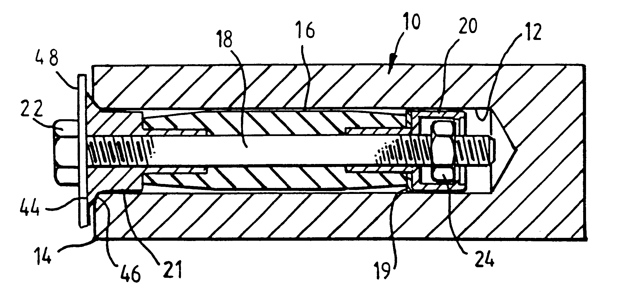
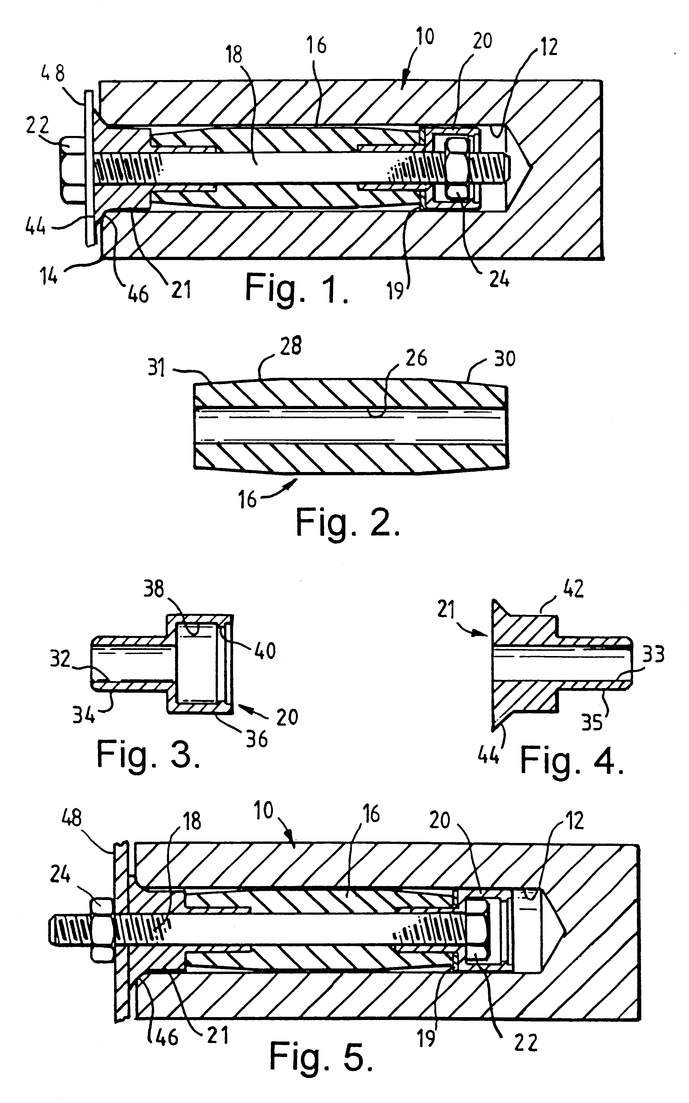
Reference is first made to FIG. 1 of the drawings, which illustrates an anchoring device 10 in accordance with an embodiment of the present invention. The device 10 is illustrated located in a hole 12 which has been drilled into a wall 14. The device 10 comprises a rubber sleeve 16, a bolt 18 extending through the sleeve 16, and first and second stoppers 20, 21 mounted on the bolt 18. A steel washer 19 is located between the first stopper 20 and the adjoining end of the sleeve 16. In the "loose bolt" arrangement illustrated in FIG. 1, the bolt head extends from the hole 12, while a nut 24 is located on the inner end of the bolt 18, within the first stopper 20 (FIG. 5 illustrates a "projecting bolt" arrangement, in which the bolt 18 is reversed).

Reference is now also made to FIGS. 2, 3 and 4 of the drawings, which illustrate the sleeve 16, first stopper 20 and second stopper 21, respectively. The sleeve 16 is formed of moulded natural rubber and defines a throughbore 26 of constant d...


PUM


Abstract

An anchoring device (10) comprises a resilient sleeve (16) for receiving an elongate member, such as a bolt (18), and first and second stoppers (20,21) for location on the bolt at respective ends of the sleeve. Movement of the stoppers (20,21) towards one another causes the sleeve (16) to expand radially. The inner first stopper (20) may engage one of the bolt head (22) and nut (24) to resist relative rotation thereof. Alternatively, the inner first stopper may be threaded.

Description

This invention relates to an anchoring device, and in particular but not exclusively to an expansible bolt anchoring device.BACKGROUND OF THE INVENTIONSExpansible bolt anchoring devices are widely used for attaching articles to, for example, the surfaces of masonry or brick walls or structures. A typical anchoring device comprises a segmented right cylindrical shell, and an expansion member located in the shell. The expansion member may be in the form of a nut mounted on the bolt (a "loose bolt" anchor) or may form the head of the bolt (a "projecting bolt" anchor). The expansion member is initially positioned at the inner end of the segmented shell such that rotation of the bolt, or rotation of a nut on the shank of the bolt, will draw the expansion member into the shell and radially expand the shell. Thus, when the device is located in a hole of corresponding diameter to the segmented shell, tightening the bolt or nut expands the shell radially to engage the hole wall.Tightening of...

Claims


Application Information

Patent Timeline
IPC IPC(8): F16B13/04F16B13/08
CPCF16B13/0841
Inventor MCALPINE, JAMES KENNETHMCALPINE, JAMES EDWARD
Owner MCALPINE
Why Eureka
Try Eureka