Roller control unit for a continuously-variable-ratio transmission

a technology of continuously variable ratio and control unit, which is applied in the direction of machines/engines, positive displacement liquid engines, gearing, etc., can solve the problems of difficult installation within the tight confines of, for example, an engine compartment, and the length of the stroke that the piston must execute in order to fully control the roller

Inactive Publication Date: 2001-08-14
TOROTRAK (DEV) LTD
View PDF11 Cites 31 Cited by
  • Summary
  • Abstract
  • Description
  • Claims
  • Application Information

AI Technical Summary

Problems solved by technology

One of the problems encountered in practice by CVT's, in which rollers are so controlled is that the length of the stroke that the piston must execute in order fully to control the roller is relatively long.
Consequently, the housing for the piston / cylinder is of such a length that it can be difficult to install within the tight confines of, for example, an engine compartment.

Method used


Image

  • Roller control unit for a continuously-variable-ratio transmission
  • Roller control unit for a continuously-variable-ratio transmission
  • Roller control unit for a continuously-variable-ratio transmission

Examples


Embodiment Construction

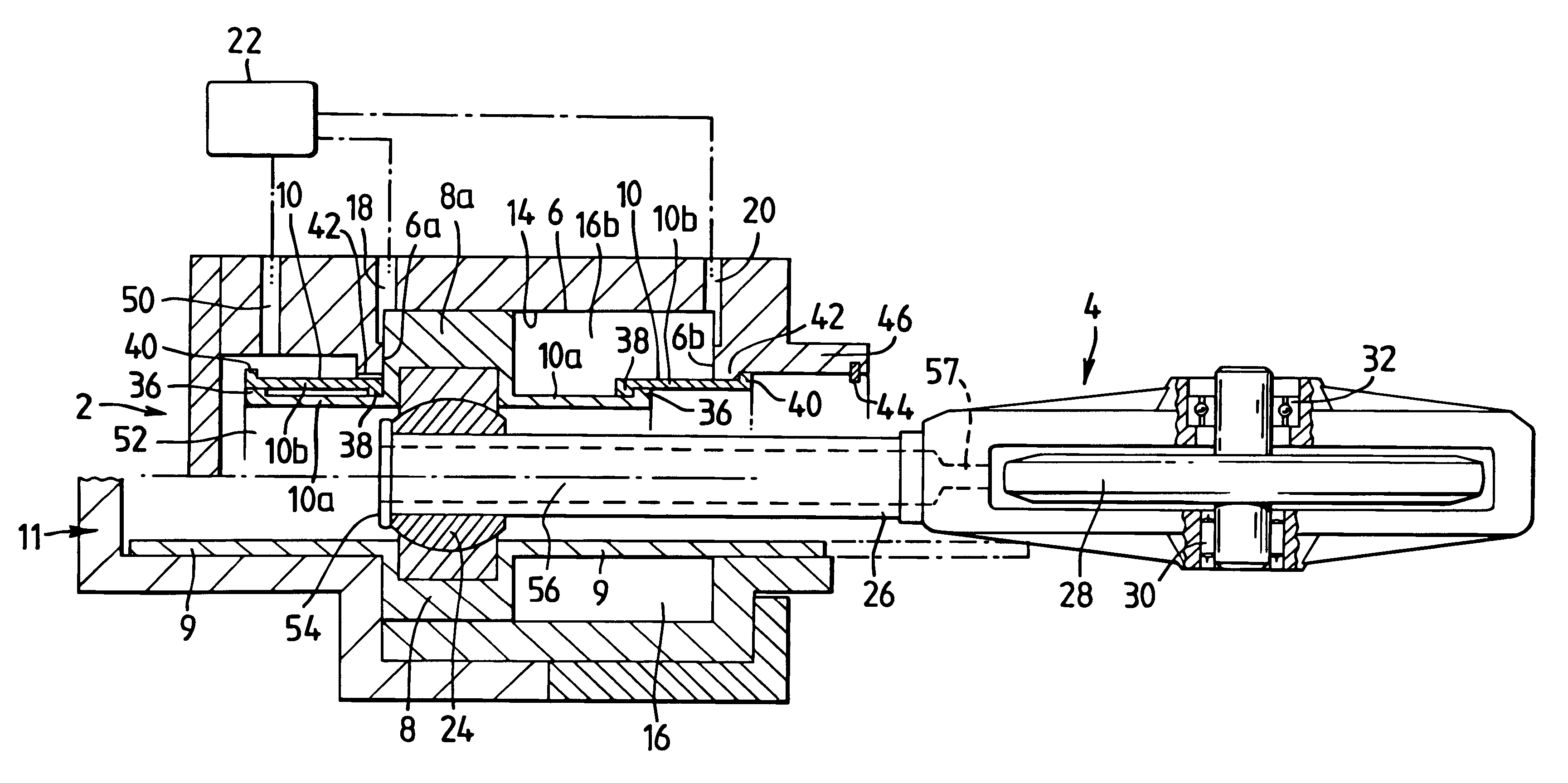
Referring to FIG. 1, there is shown a roller-control unit 2 comprising an hydraulic piston / cylinder unit coupled to an associated roller 4. The lower part of the roller control unit 2 is shown diagrammatically as a known type of unit whereas the upper part portrays the present invention. The lower portion includes a piston 8 having axially extending portions 9 which act to define one boundary of a hydraulic chamber for receiving hydraulic piston control fluid. It will be appreciated that portions 9 must be sufficiently long as to ensure that they maintain contact with the cylinder at both extremes of the piston travel. Consequently, portions 9 protrude from the roller unit for a significant distance in order to accommodate the movement of the piston and the housing 11 in which the unit is housed is, by necessity, somewhat larger than might be desired.

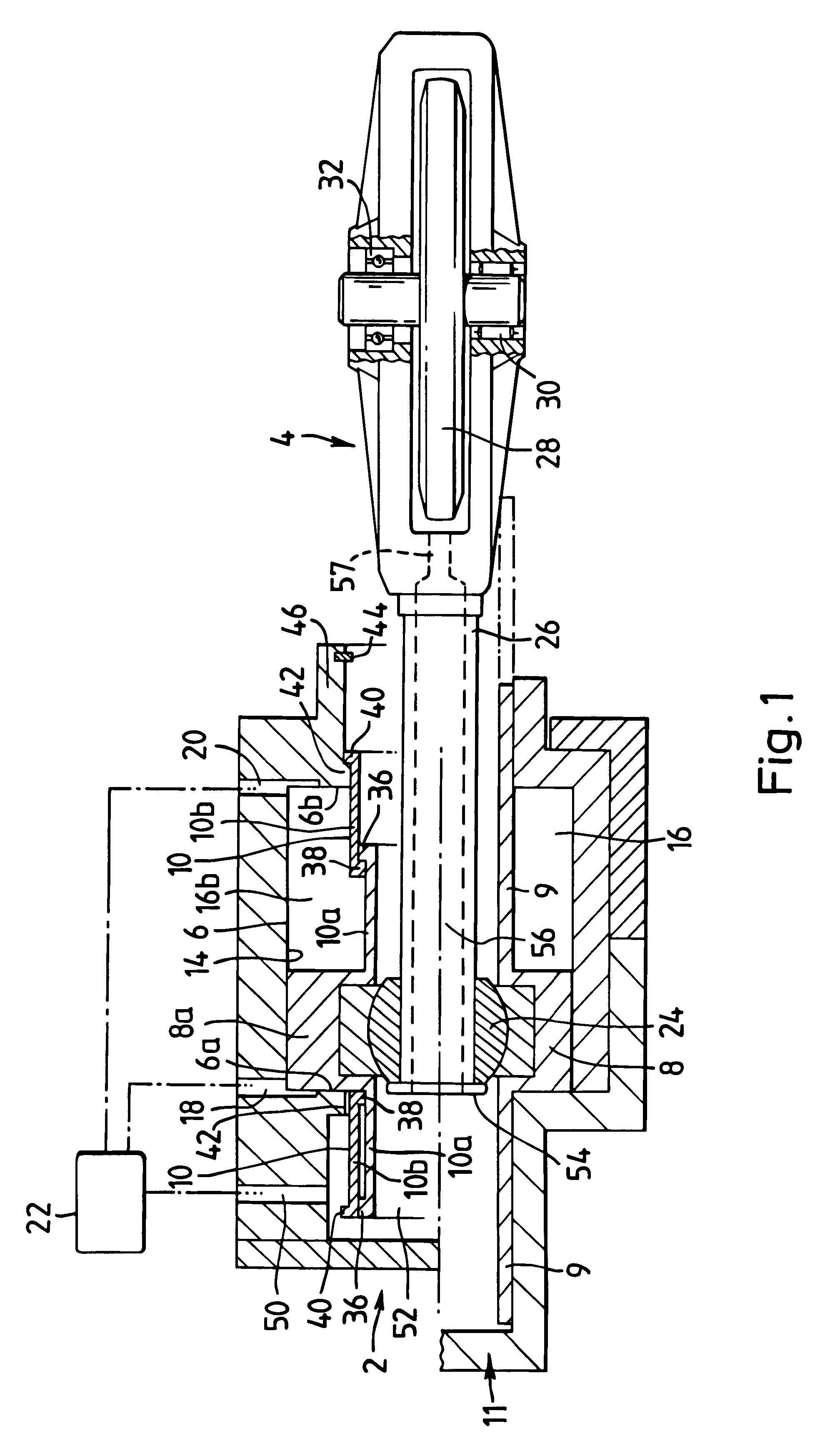
Referring now to the upper part of FIG. 1, a roller control unit 2 according to the present invention includes a cylinder 6 which rece...


PUM


Abstract

A roller control unit (2) for a continuously-variable-ratio transmission includes a cylinder (6) having a cylinder wall and an end wall; and a piston (8), within the cylinder (6) and to which the roller assembly (4) is connected for movement therewith, said unit includes an axially extending shroud (10) of variable length extending between the piston (8) and the end wall, thereby to define in combination with the piston (8) and cylinder (6) a chamber (16) for receiving hydraulic fluid, and in which the shroud (10) comprises a telescopic shroud which in a first position of the piston (8) is extended and in a second position of the piston (8) is retracted.

Description

1. Field of the InventionThis invention relates to continuously-variable-ratio transmissions ("CVT's") of the toroidal-race rolling-traction type, and in particular to roller-control units of the kind by which the orientation of the traction-transmitting rollers may be controlled hydraulically, by means of the direct connection of the carriage of each roller to a piston, movable within a hydraulic cylinder connected to a controlled source of variable fluid pressure.2. Discussion of Prior ArtSeveral patent publications of recent years, of which WO90 / 05860 is an example, describe toroidal-race transmissions in which direct connection of each roller to a piston subject to controlled hydraulic pressure suffices to maintain the angular orientation of each roller--and thus the ratio transmitted by it from an input disc--at the appropriate value at all times. The key to the efficacy of such an apparently simple method of roller control is that for any given combination of the essential par...

Claims


Application Information

Patent Timeline
Patent Type & Authority Patents(United States)
IPC IPC(8): F16H61/664F16H15/38F16H15/32F16H61/66
CPCF16H15/38F16H61/664F16H57/049
Inventor DUTSON, BRIAN JOSEPH
Owner TOROTRAK (DEV) LTD
Why Eureka
Try Eureka