Fuel tank for a motor vehicle
a technology for fuel tanks and motor vehicles, applied in the direction of positive displacement liquid engines, piston pumps, instruments, etc., can solve the problems of complex logistics of fuel tanks, high cost, and large number of components, and achieve the effect of cost-effective mounting procedures and simplified logistics
- Summary
- Abstract
- Description
- Claims
- Application Information
AI Technical Summary
Benefits of technology
Problems solved by technology
Method used
Image

Examples
Embodiment Construction
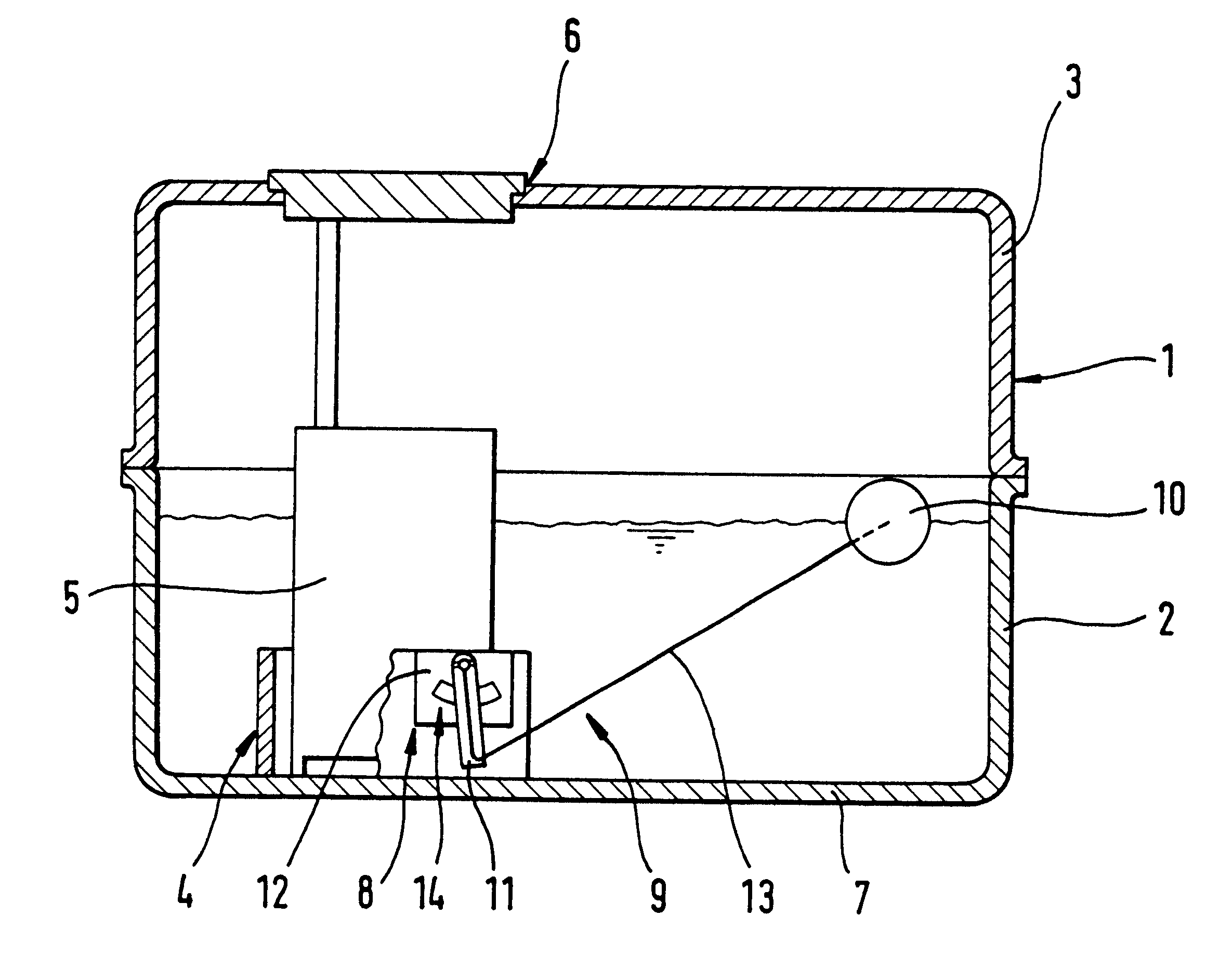
According to a preferred embodiment of the present invention, the carrier is designed to be in one piece with a wall of the baffle or with another feed unit component prestressed against the bottom of the fuel tank. This allows the fuel tank according to the present invention to have a particularly small number of components. The lever arm of the fuel level sensor can thereby be inserted directly into the fuel tank or be fastened to the feed unit before the latter is mounted in the fuel tank. Designing the carrier in one piece with the baffle or with a component of the feed unit allows the manufacture of the fuel tank according to the present invention to be simplified, since latching hooks or the like for fastening the carrier are not necessary. The manufacture of the fuel tank becomes particularly cost-effective as a result.
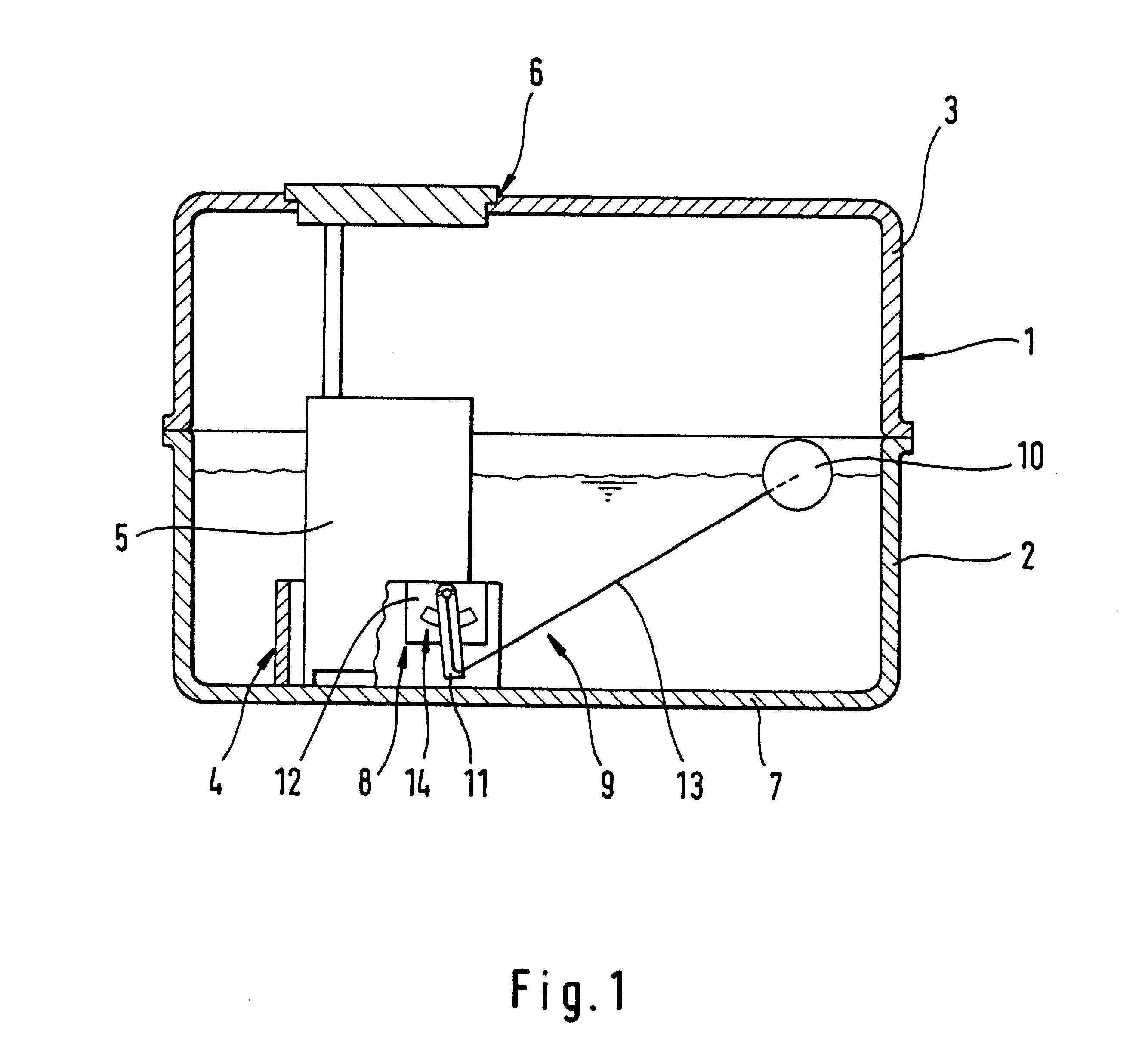
According to another advantageous development of the invention, it is possible in a simple way to ensure the lever arm engages round in the region of its mount...
PUM
 Abstract
Description
Claims
Application Information
 - Generate Ideas
- Intellectual Property
- Life Sciences
- Materials
- Tech Scout
- Unparalleled Data Quality
- Higher Quality Content
- 60% Fewer Hallucinations
Browse by: Latest US Patents, China's latest patents, Technical Efficacy Thesaurus, Application Domain, Technology Topic, Popular Technical Reports.
© 2025 PatSnap. All rights reserved.Legal|Privacy policy|Modern Slavery Act Transparency Statement|Sitemap|About US| Contact US: help@patsnap.com