Optical transmission device for bi-directional optical communication

a transmission device and optical communication technology, applied in the field of optical transmission devices for bi-directional optical communication, can solve the problems of inability to perform normal communications between optical transmission devices, inability to perform branching/insertion of optical signals transmitted from the reverse direction, and reduced throughpu

Inactive Publication Date: 2001-08-21
FUJITSU LTD
View PDF5 Cites 81 Cited by
  • Summary
  • Abstract
  • Description
  • Claims
  • Application Information

AI Technical Summary

Benefits of technology

With the optical transmission device of the present invention used for bi-directional optical communications, which is constructed in the foregoing manner, the flows of optical signals transmitted in two ways can be unified in a signal direction by changing the network configuration. Accordingly, the invention is advantageous in that branching / insertion of optical signals transmitted in two ways or returning thereof in emergency can be normally performed by using the existing optical transmission device for uni-directional optical communications and an optical transmission device for bi-directional optical communications can be provided at low costs.
As described above, in the wavelength-division multiplexing communication system 51 employing the bi-directional wavelength-division multiplexing system which allows optical signals to be transmitted in two ways, communications can be continued even if a failure occurs. Accordingly, compared with the wavelength-division multiplexing communication system 50 employing the uni-directional wavelength-division multiplexing system, the wavelength-division multiplexing communication system 51 is advantageous in that communications may be performed without switching to the optical fiber 81A' or 81B' for emergency or limiting transmission capacity.

Problems solved by technology

However, in the wavelength-division multiplexing communication system 50, it may become impossible to perform normal communications between the optical transmission devices 501 and 502.
In this case, however, since the foregoing remaining half of the transmission capacity is exclusively used for a failed area, throughput may be reduced.
Furthermore, assuming that the uni-directional optical ADM devices 501 to 505 are constructed by using the foregoing AOTF, since a port for branching / insertion processing is predetermined in the AOTF, branching / insertion cannot be performed for optical signals transmitted from the reverse direction.

Method used


Image

  • Optical transmission device for bi-directional optical communication
  • Optical transmission device for bi-directional optical communication
  • Optical transmission device for bi-directional optical communication

Examples


first embodiment

the present invention will now be described with reference to the accompanying drawings.

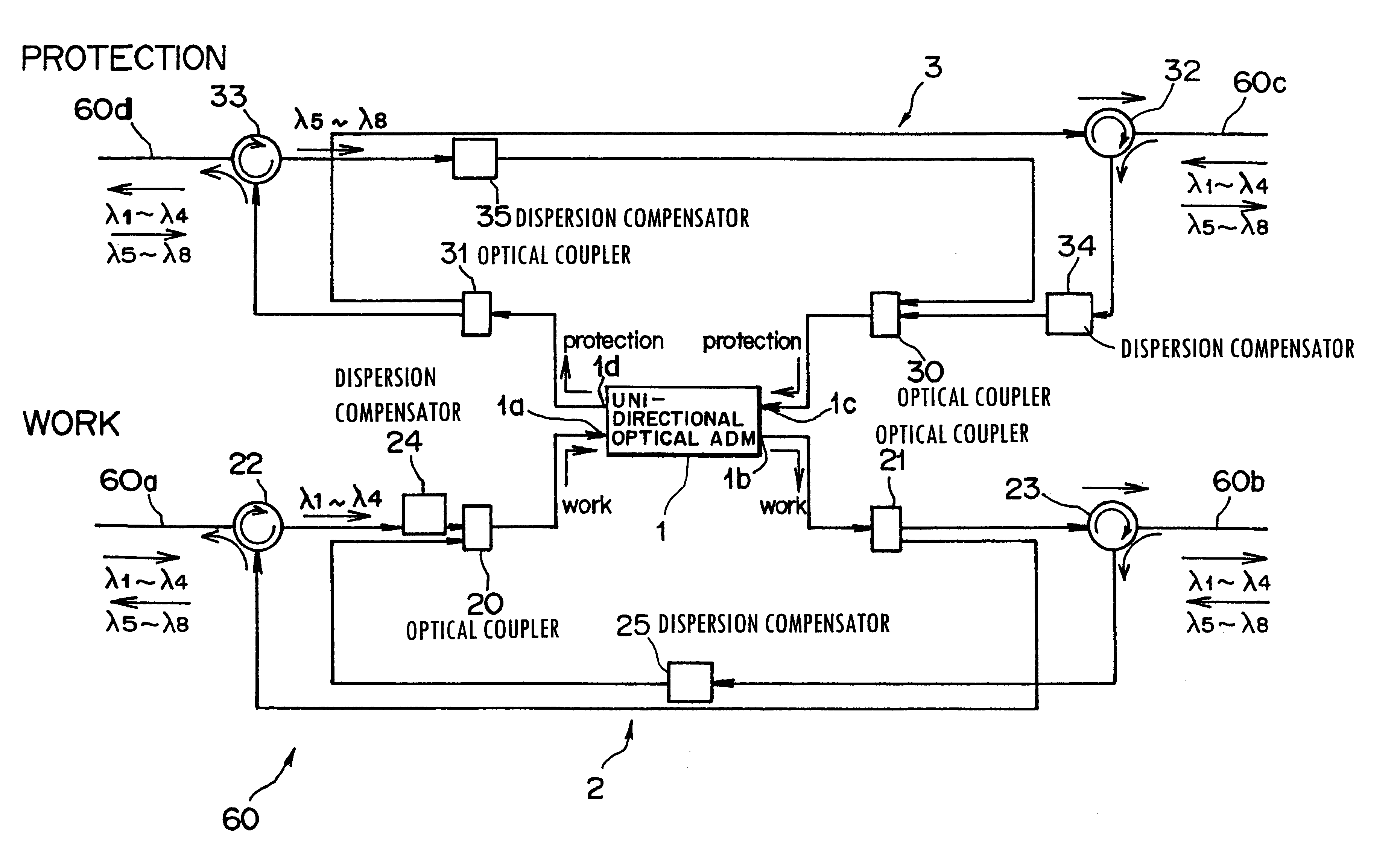
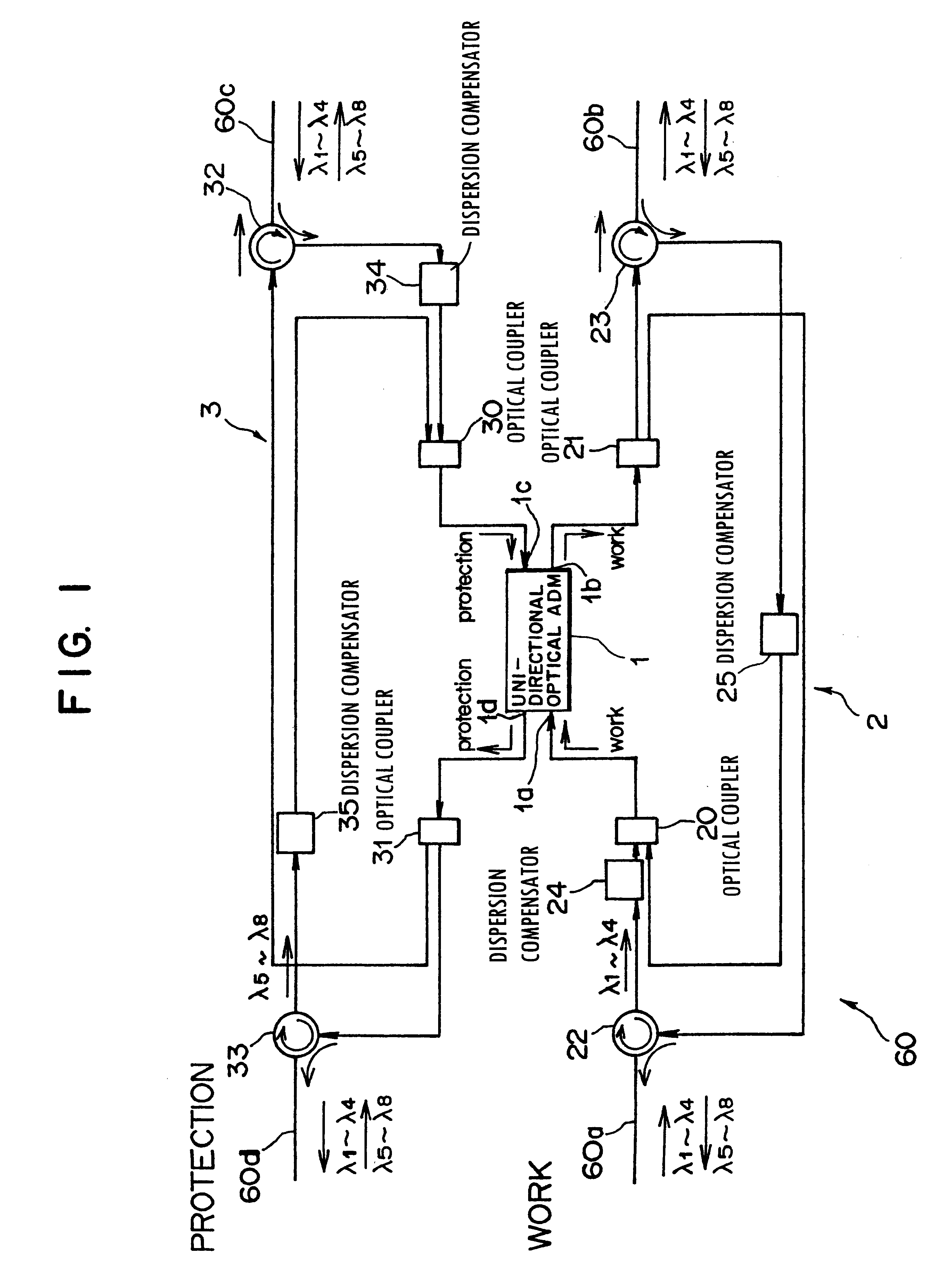
Referring to FIG. 1 which is a block diagram, there is shown a constitution of an optical transmission device used for bi-directional optical communications according to the first embodiment of the present invention. A bi-directional optical communication optical transmission device 60 shown in FIG. 1 is positioned between optical fibers (bi-directional communication optical transmission lines) 60a and 60b for performing bi-directional optical communications by transmitting optical signals having wavelengths different between clockwise and counterclockwise directions. The optical transmission device 60 performs specified optical transmission processing for the optical signals transmitted through these optical fibers 60a and 60b. The optical transmission device 60 comprises an optical ADM device 1 and a first direction changing unit 2.

The optical ADM device (uni-directional optical ADM, uni-direct...

first modified example

(b) First Modified Example of the First Embodiment

According to the foregoing bi-directional communication optical transmission device 60 of the first embodiment, in the first direction changing unit 2, optical signals (first and second optical signals) transmitted in two ways are branched by using the optical circulators 22 and 23. However, instead of the optical circulators 22 and 23, optical couplers may be used for the same purpose. For example, in the case of a bi-directional communication optical transmission device 61 shown in FIG. 9, in a first direction changing unit 2A, optical signals are branched by using optical couplers 26 and 27. These optical couplers 26 and 27 are respectively constructed as wavelength-division multiplexing / demultiplexing type couplers.

Specifically, the optical coupler 26 branches the first optical signals from the optical fiber 60a through the distribution compensator 24 to the optical coupler 20 and the second optical signals demultiplexed by the o...

second modified example

(c) Second Modified Example of the First Embodiment

Referring to FIG. 10 which is a block diagram, there is shown a second modified example of the bi-directional communication optical transmission device of the first embodiment.

In the foregoing bi-directional communication optical transmission devices 60 and 61, the bi-directional flows of the optical signals are unified in a single direct-on by using the 1.times.2 WDM optical couplers 20 and 21 (optical couplers 30 and 31 in an emergency). However, in the second modified example, as shown in FIG. 10, a bi-directional communication optical transmission device 62 is constructed by using a 2.times.2 WDM optical coupler 28 (2.times.2WDM optical coupler 38 in an emergency).

Specifically, the bi-directional communication optical transmission device 62 shown in FIG. 10 is positioned between normal-time optical fibers 60a' and 60b' and between emergency optical fibers 60c' and 60d', and performs specified optical transmission processing for ...


PUM


Abstract

This invention discloses an optical transmission device used for bi-directional optical communications. The optical transmission device comprises a uni-directional optical signal processing unit for performing specified optical signal processing for optical signals transmitted in a single direction and a uni-direction / bi-direction changing unit for unifying the flows of clockwise and counterclockwise optical signals in a single direction, inputting these flow-unified optical signals to the uni-directional optical signal processing unit and dividing the flow of optical signals from the uni-directional optical signal processing unit between clockwise and counterclockwise directions. Bi-directional wavelength-division multiplexing optical communications can be performed by unifying the transmission routes (flows) of optical signals transmitted in two ways in a single direction and using the existing optical transmission device for uni-directional optical communications.

Description

(1) Field of the InventionThis invention relates to an optical transmission device for bi-directional optical communications, which performs bi-directional optical communications by transmitting optical signals having different wavelengths in two ways.(2) Description of the Related ArtFor a transmission type communication system designed to construct a multimedia network, an optical communication system capable of increasing transmission capacity has been used in recent years. Various multiplexing systems have been available in order to attain extra-large capacity in the optical communication system. Such multiplexing systems include, for example, a time-division multiplexing (abbreviated as TDM) transmission system, an optical time-division multiplexing (OTDM) transmission system, a wavelength-division multiplexing (WDM) transmission system, and so on.Among these multiplexing systems, the WDM transmission system is promising, because it facilitates flexible construction of an optic...

Claims


Application Information

Patent Timeline
Patent Type & Authority Patents(United States)
IPC IPC(8): H04J14/02H04B10/00H04J14/00H04B10/032H04B10/035H04B10/07H04B10/2519H04B10/2525H04B10/297
CPCH04J14/0212H04J14/0291H04J14/0213H04J14/0204H04J14/0205H04J14/0206H04J14/0216H04J14/0221H04J14/0283
Inventor KAI, YUTAKACHIKAMA, TERUMI
Owner FUJITSU LTD
Why Eureka
Try Eureka