Light fixture for shelving

a technology for light fixtures and shelves, applied in the field of light fixtures, can solve the problems of light bulbs that are exceedingly difficult to change, easy to be knocked off the shelf, and take a large amount of shelf space, so as to reduce heat transfer, reduce heat transfer, and reduce the effect of ligh

Inactive Publication Date: 2001-09-04
STRAAT PATRICIA ANN
View PDF4 Cites 87 Cited by
  • Summary
  • Abstract
  • Description
  • Claims
  • Application Information

AI Technical Summary

Benefits of technology

In accordance with one aspect of this embodiment of the present invention, a light is positioned within the airgap to provide backlighting. Further according to this embodiment of the present invention, a light holding bracket is provided for mounting the light. The light holding bracket is secured to the light support member and may be secured to the light support member by at least one strap. This at least one strap may be preferably loosened to allow precision positioning of the light holding bracket along longitudinal centerline of the light support member.
In accordance with yet another aspect of this embodiment of the present invention, the light holding bracket preferably has a long side having an inner and an outer surface, an a short side having an inside and an outside surface, the outer surface having insulation attached thereon to reduce heat transfer from the light to the light support member.
In still yet another embodiment of the present invention a light fixture is provided having a light source, and a bracket for holding the light source, the light source being positioned within the bracket to provide substantially bi-directional light. According to anot...

Problems solved by technology

This had the disadvantages of being easily knocked off the shelf and of taking a large amount of shelf space.
Prior methods of shelf lighting include light bulbs that are exceedingly hard to change as the lights were fixed to the shelf or display unit.
A further limitation in prior display units includes problems in illuminating opaque shelves.
In addition to...

Method used


Image

  • Light fixture for shelving
  • Light fixture for shelving
  • Light fixture for shelving

Examples


Embodiment Construction

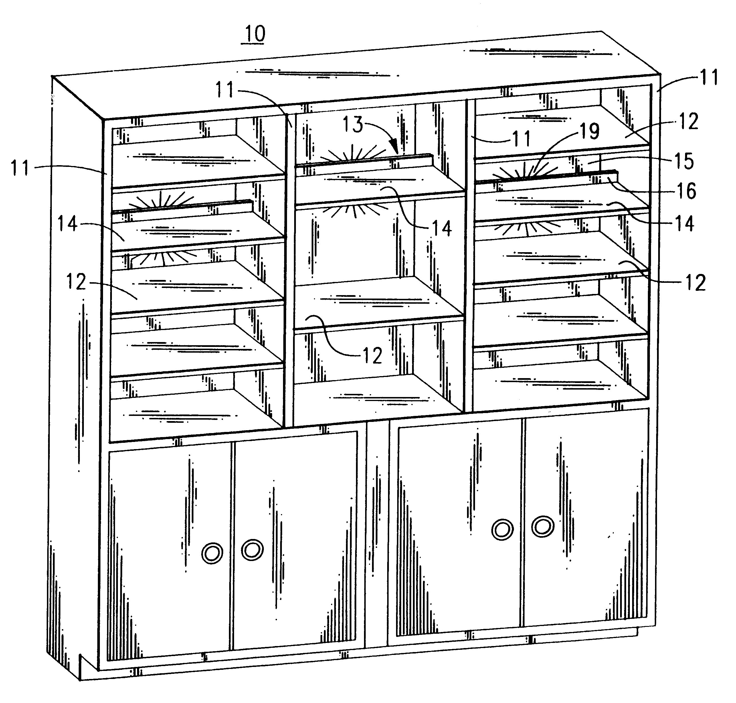
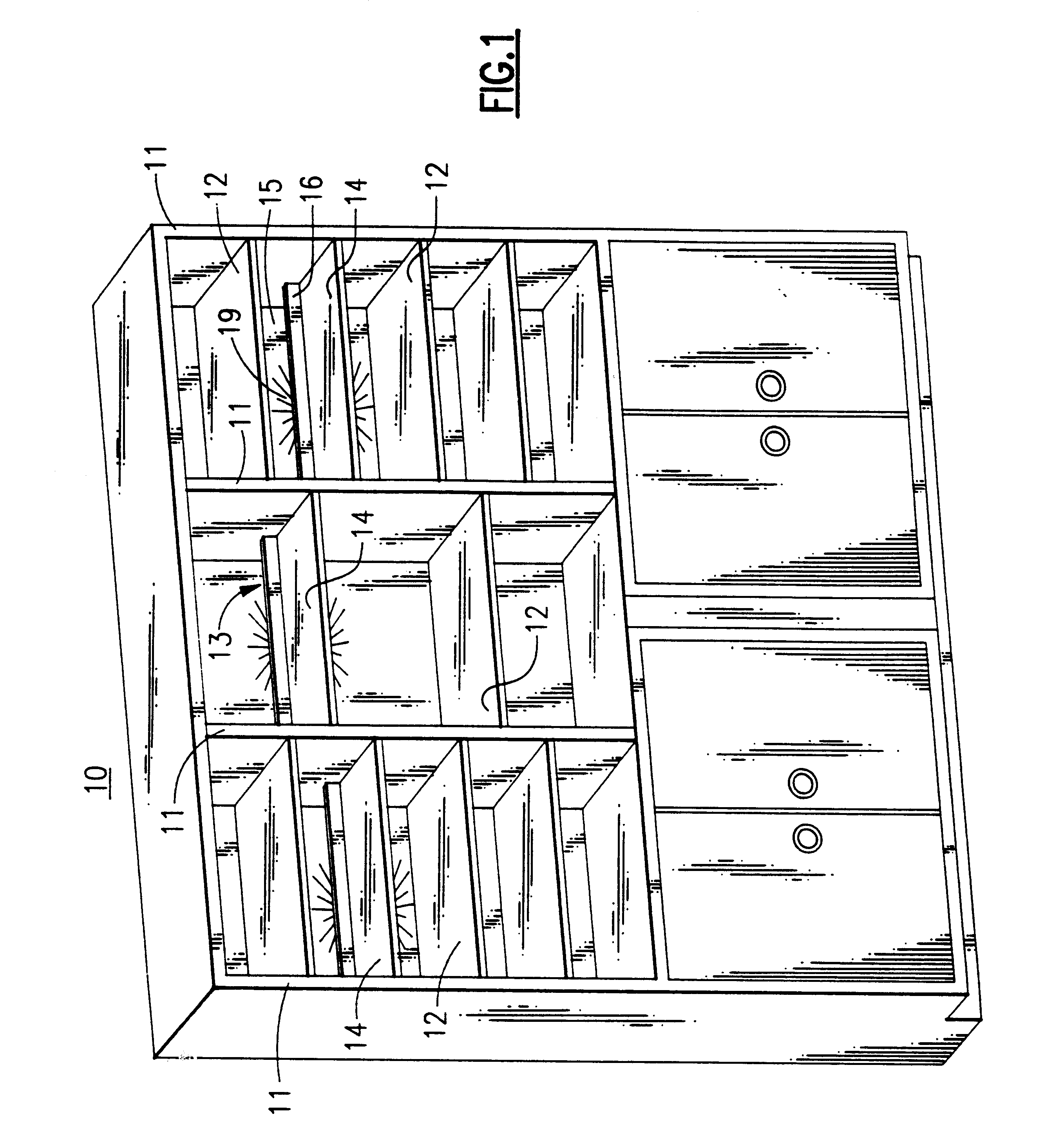
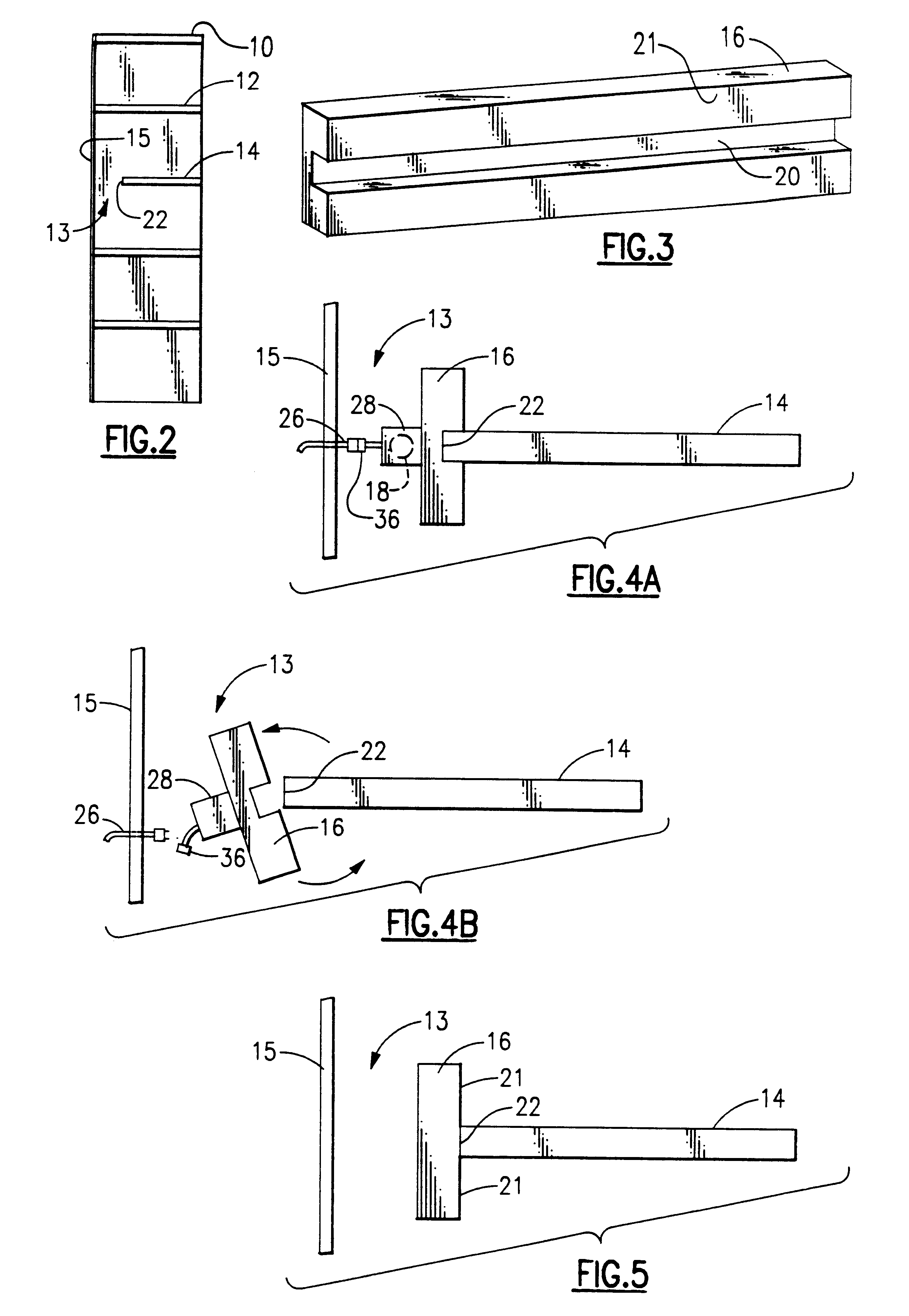
Referring now to FIG. 1, there is shown a shelving unit 10 in accordance with the present invention. The shelving unit 10 contains several shelves 12 and three shortened shelves 14. The shortened shelf 14 has an air-gap 13 between its back edge 22, FIG. 2, and a rear wall 15 of the shelving unit 10. On the back edge 22 of the shortened shelf 14 there is a light support member 16 (FIG. 3) for holding a light assembly containing light 18, FIGS. 4A, 9, and 12. The light 18 provides bi-directional light 19 to the air-gap 13 and the normal shelf 12 as well as bi-directional light 19 above and below the shortened shelf 14. Through reflection and diffusion, bi-directional light 19 is also provided to the shortened shelf 14. Bi-directional as used herein, is meant to include light directed substantially upwardly and downwardly relative to shortened shelf 14 and light support member 16. The primary effect of the bi-directional light 19 is to backlight the shortened shelf 14 and any objects p...


PUM


Abstract

A display assembly having at least one shelf. The back edge of the shelf being permanently affixed to a light support member. The light support member extends above and below the shelf. The light support member is spaced away from a support surface to provide an air gap between the light support member and the support surface. A light is attached to the light support member such that it is positioned within the air gap. Thereby the light provides backlighting. The light may be attached to the light support member by way of a bracket. The bracket can be positioned by way of mounting straps. The bracket may be J shaped, U shaped, rectangular shaped or any other suitable shape for producing substantially bidirectional light. The shelf can be either fixed or removable.

Description

1. Field of the InventionThis invention relates in general to light fixtures, and in particular, to light fixtures associated with shelving. More specifically, but without restriction to the particular embodiments hereinafter described in accordance with the best mode of practice, this invention relates to both a quick-release light fixture that casts multi-directional light from behind an opaque shelf and a fixed light fixture that casts multi-directional light from behind a shelf.2. Discussion of the Related ArtIn the modern world, humankind has increasingly populated his environment. As the population has grown, the space for each individual has decreased. As each individual office and home space has become smaller, so has the furniture that is used in those spaces. One particular kind of furnishing which has decreased in size includes display shelves, book shelves, and china cabinets. In the past, book shelves and china cabinets were very large pieces of furniture that were not ...

Claims


Application Information

Patent Timeline
IPC IPC(8): A47F11/00A47F11/10A47F5/00F21V33/00F21V21/08F21S8/00
CPCA47B97/00A47F5/0018A47F11/10F21V17/108F21V21/08F21V33/0012F21S8/00F21W2131/301
Inventor STRAAT, PATRICIA ANN
Owner STRAAT PATRICIA ANN
Why Eureka
Try Eureka