Apparatus and method of measuring outer diameter of worked portion at pipe end

a technology for working parts and apparatuses, which is applied in the direction of mechanical diameter measurement, measurement gauges, instruments, etc., can solve the problems of high cost, high labor intensity, and large labor intensity of workers, and achieve the effect of rapid and accurate measuremen

Inactive Publication Date: 2001-09-11
VALLOUREC OIL & GAS FRANCE SAS
View PDF7 Cites 17 Cited by
  • Summary
  • Abstract
  • Description
  • Claims
  • Application Information

AI Technical Summary

Benefits of technology

A second object of the present invention is to provide a method for rapidly and accurately measuring an outer diameter of the worked portion at the end of a pipe by use of the aforementioned apparatus.

Problems solved by technology

Such a thread requires durability against repeated use, and a portion which is joined by the thread, also requires high air tightness.
(1) A number of gauges need to be prepared for each pipe size and also for each measuring position. Therefore, the expenditure for their fabrication would run up and this also takes a lot of trouble due to the checking operation for quality control of the gauges.
(2) Since it needs to perform the measurement with fitting the gauge onto the measuring position from the outside, this occasionally causes to make some defects on the peripheral of the pipe.
(3) In a case that the thread worked portion is out of the complete round, the measurement error would be increased.
(4) Since the maximum size of the outer diameter is measured by making a reference portion of the gauge contact at the pipe end, it needs to turn the gauge around with making the reference portion serve as a fulcrum. Accordingly, the measurement attitude could become unstable, and this tends to cause measurement error.
(5) Since the outer diameter of the designated portion is measured at several points and these sizes are visually read, a continuous and rapid measurement cannot be carried out.
(6) Since plural designated portions need to be measured with respective particular gauges, the designated portions cannot simultaneously be measured.
As described above, any conventional measuring methods are inefficiently performed by manual procedures, and it is also difficult to measure with high accuracy.

Method used


Image

  • Apparatus and method of measuring outer diameter of worked portion at pipe end
  • Apparatus and method of measuring outer diameter of worked portion at pipe end
  • Apparatus and method of measuring outer diameter of worked portion at pipe end

Examples


Embodiment Construction

Hereinafter, the measuring apparatus and the measuring method of the present invention will be described in detail with reference to the drawings showing their best mode.

1. The Apparatus of the Present Invention

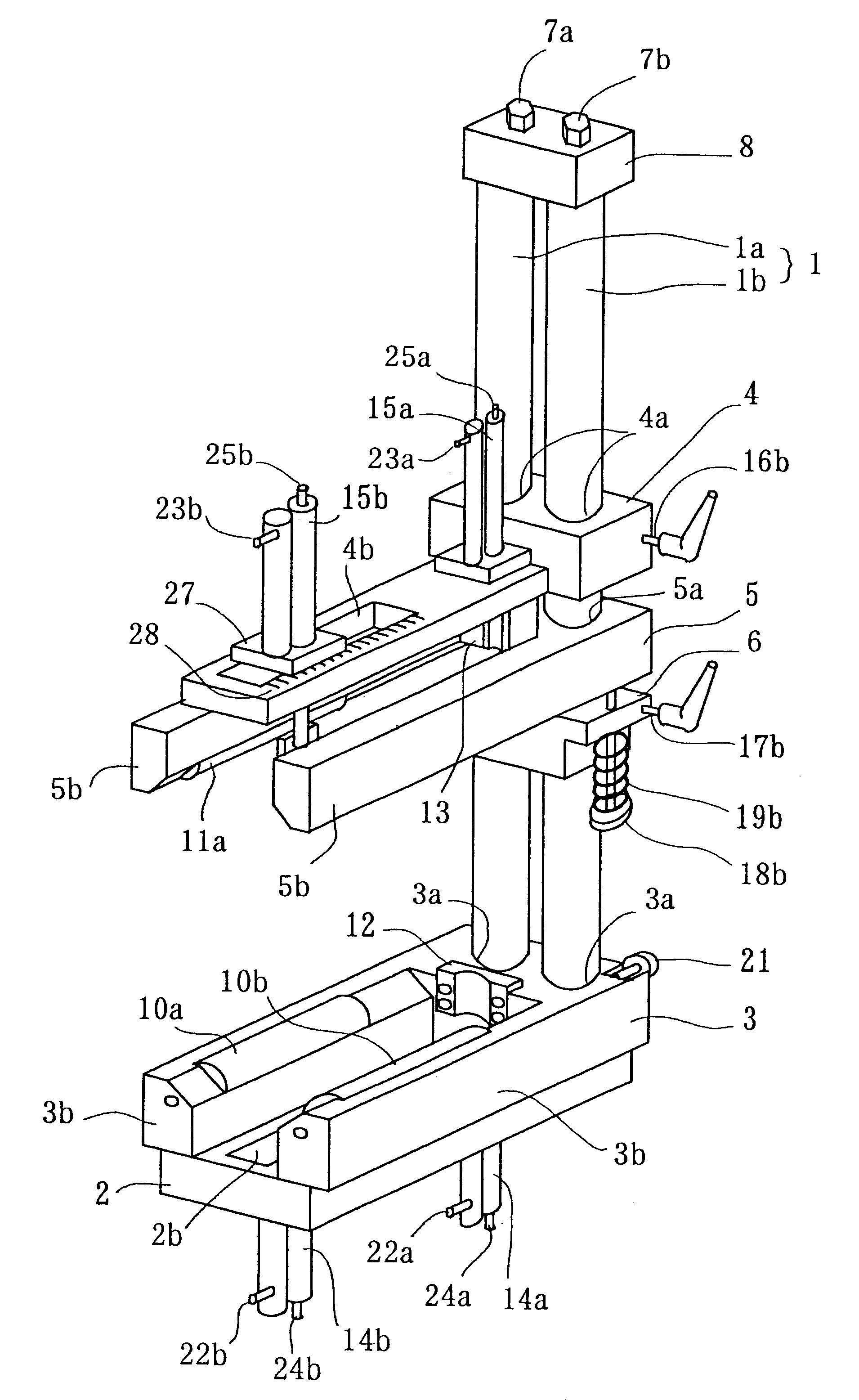
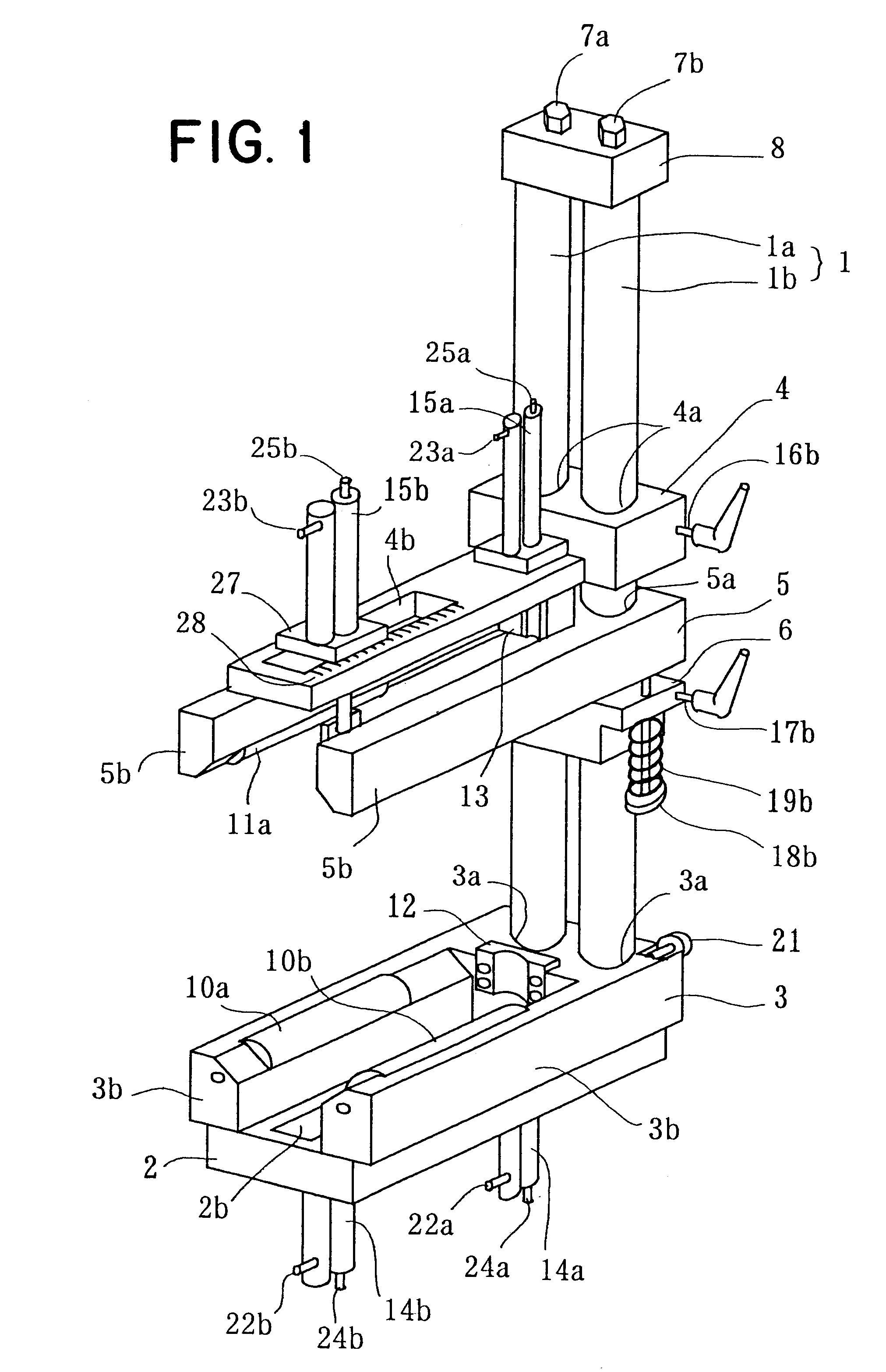
In FIG. 1, a main arm 1, for example, comprises two parallel shafts 1a and 1b whose upper ends are secured to a fixing bracket 8 by bolts 7a and 7b respectively. A lower gauge head support arm 2 and a bearing roller arm 3 are disposed in a horizontal position at the lower end portion of this main arm 1, that is, both arms 2 and 3 and the main arm 1 are orthogonally arranged.

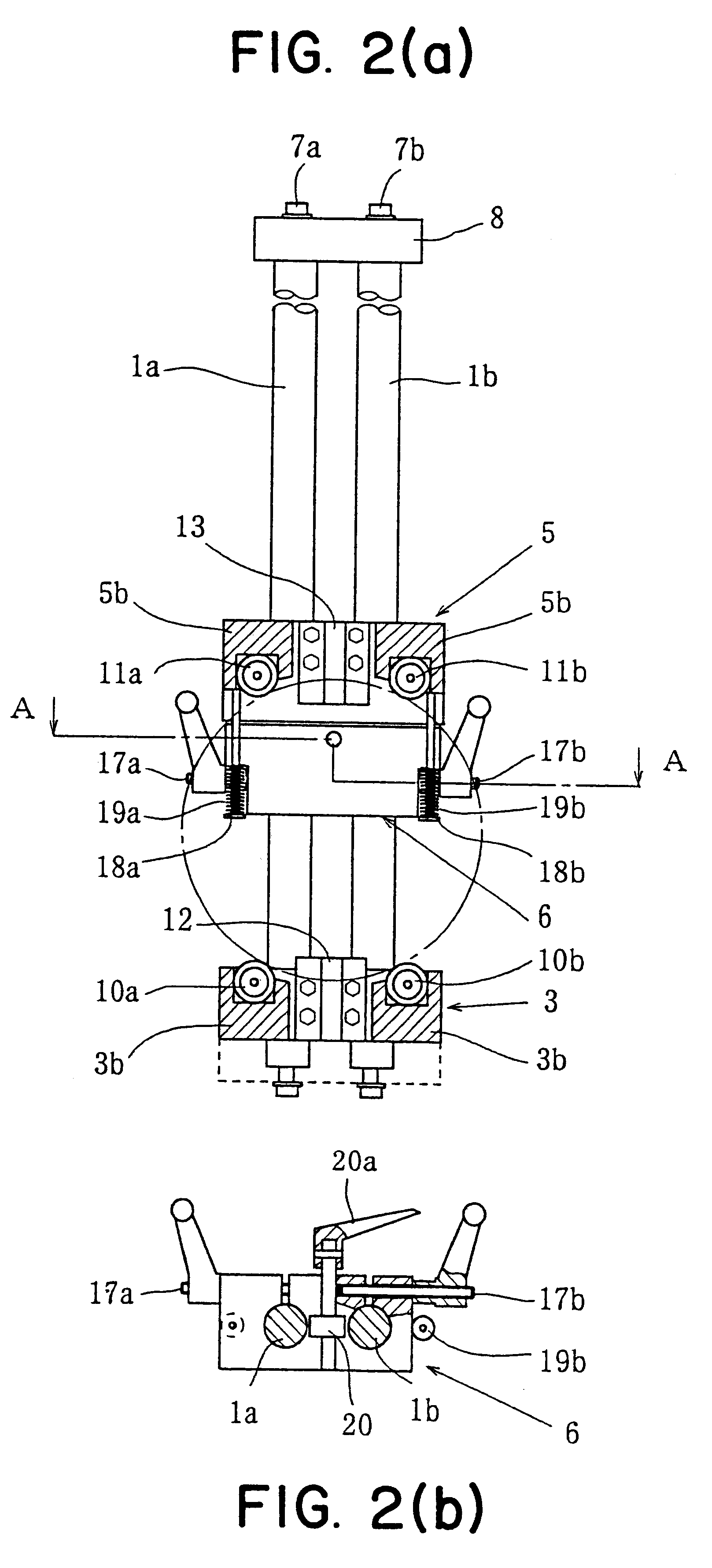
An upper gauge head support arm 4, a presser roller arm 5 and a position-fixing bracket 6 are located at an upper side of the main arm 1. These are mounted on the shaft 1a and 1b in parallel with the lower gauge head support arm 2 and the bearing roller arm 3, and are slidably guided on the shaft 1a and 1b.

The bearing roller arm 3 and the presser roller arm 5 are formed in a U-shape respectively having two...


PUM


Abstract

An apparatus and a method are provided for rapidly and precisely measuring an outer diameter of a pipe end portion of various sizes of pipes. This apparatus includes a main arm (1), a lower gauge head support arm (2), a bearing roller arm (3), an upper gauge head supporting arm (4), a presser roller arm (5), an position-fixing bracket (6), a gage head (14b) which is horizontally and vertically movable while being supported by the arm (2), and a gauge head (15b) which is also horizontally and vertically movable while being supported by the arm (4). In addition, A gauge heads (14a) and (15a) are provided, both of which are vertically movable.An object is measured in its outer diameter by the gauge heads while being rotatably held by rollers (10a, 10b, 11a and 11b) of the arm (3) and (5). Such a measurement can simultaneously be carried out at two longitudinal portions of the measured object.

Description

The present invention relates to an apparatus for measuring the outer diameter of a worked portion at the end of a pipe end, and a method thereof. The pipe, for example, is an oil well pipe. A thread for coupling is formed at an end portion of the oil well pipe. The apparatus and the method of the present invention are suitable for measuring the outer diameter dimension after a thread working is applied.FIG. 5 is a sectional view showing a typical example of a method for joining oil well pipes. FIG.5(a) shows one type in which two pipes P.sub.1 and P.sub.2 are jointed to each other by use of a coupler C. In this type, a thread portion S, having a mail thread, is provided around each outer peripheral surface of the ends of the two pipes P.sub.1 and P.sub.2. The two pipes are joined together by screwing the male thread into the mating female thread provided around an inner peripheral surface of the coupler C. In the type shown in FIG.5 (b), a female thread is provided around an inner ...

Claims


Application Information

Patent Timeline
Patent Type & Authority Patents(United States)
IPC IPC(8): G01B5/08
CPCG01B5/08
Inventor IWAMOTO, MICHIHIKO
Owner VALLOUREC OIL & GAS FRANCE SAS
Why Eureka
Try Eureka