Flatness measurement system for metal strip

a metal strip and flatness measurement technology, applied in the direction of measuring devices, instruments, profile control devices, etc., can solve the problems of inability to contact measurement on the end faces of coils formed in coilers, inability to accurately measure the flatness of strips, etc., to achieve simple and effective strip flatness measurement, improve the quality of strips, and permit fine control of rolling and/or coiling parameters

Inactive Publication Date: 2001-09-11
THYSSEN KRUPP STAHL AG +1
View PDF14 Cites 48 Cited by
  • Summary
  • Abstract
  • Description
  • Claims
  • Application Information

AI Technical Summary

Benefits of technology

The object of the invention is to provide a system which allows strep quality to be improved by a simple and effective measurement of the strip flatness and permits fine control of the rolling and / or coiling parameters.
Deviations of the strip surface from the ideal plane bring about a change in the spacing between the lines in the region of the unevenness. This change is recorded by the camera. It can be converted by calculation in a simple manner into differences in height by a comparison with an ideal pattern.
The system in accordance with the invention makes possible a rapid determination of the actual height differences of the strip surface and in this way permits measurement of continuous lengths of strip in real time. This has the advantage that the measurement results permit the rolling parameters to be adapted immediately after the appearance of an unevenness.

Problems solved by technology

The contact measurement usually used in cold strip mills is only possible in the hot strip field at the expense of substantial outlay on maintenance, because of the high strip temperature of from about 1000.degree. C.
Contact measurement on the end faces of a coil being formed in a coiler is also not possible.
It is therefore difficult, if not completely impossible, to coil strip in such a way that in the coil every turn lies exactly over the preceding one so that flat end faces are obtained.
And even in cold strip mills efforts are made to avoid contact measurement, since the mechanical measuring elements have only a limited life.
Nevertheless, in this method the regions between the points of light are not detected an in the case of continuous strip from strip-shaped measurement gaps in which the flatness is not determined.
Moreover, this can result in measurement errors, for example through wobbling or flattering of the strip being detected by the measuring method as uneveness of the strip.
However, its use involves problems, particularly in a hot strip mill.
But in a rolling mill train rapid results are precisely what is required from measurements, since otherwise it is hardly possible to use the measurement for direct adjustmente of the rolling parameters so as to improve the flatness of the continuous strip.
Moreover for industrial application the fine interference patterns are lacking in contrast and intensity.
In the case of conventional metal strip mill trains, in which the strip flatness is measured by one of the above-mentioned methods, departures from flatness are not measured from the cooling line, and this can result in considerable loss in quality.

Method used


Image

  • Flatness measurement system for metal strip
  • Flatness measurement system for metal strip
  • Flatness measurement system for metal strip

Examples


Embodiment Construction

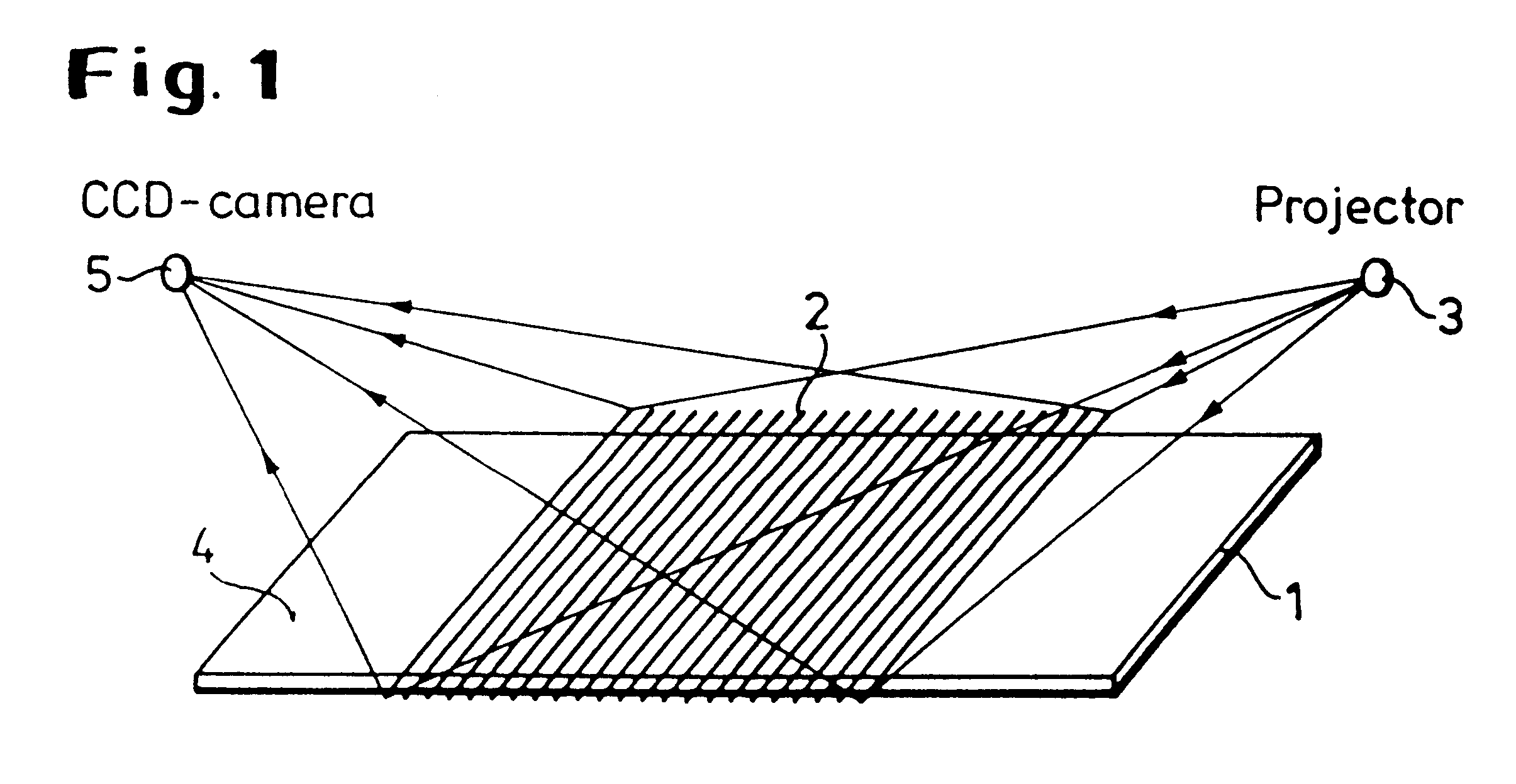
Measurement lines 2 running transverse to the strip 1 are produced on the measurement or strip surface 4 using a protector 3.

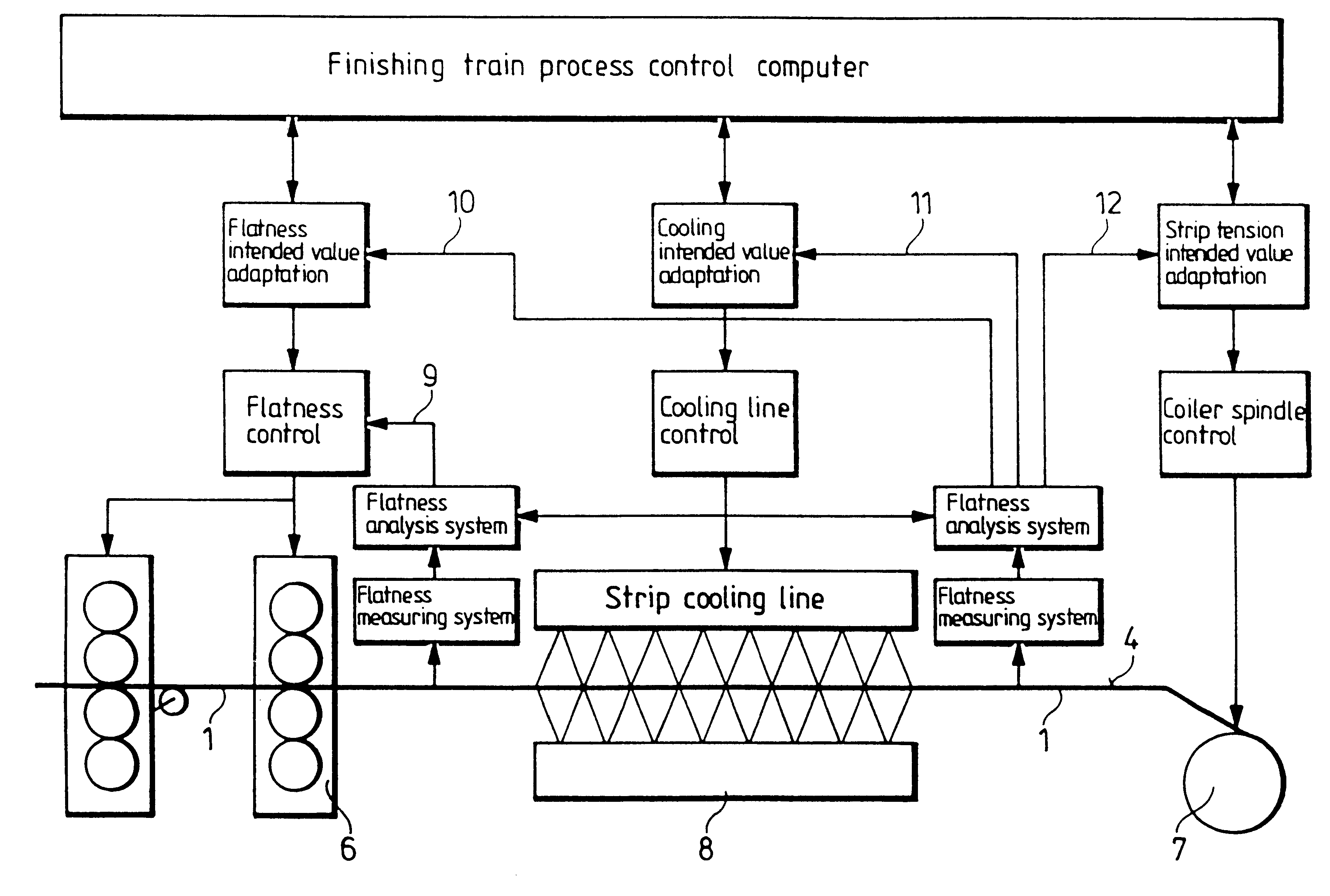
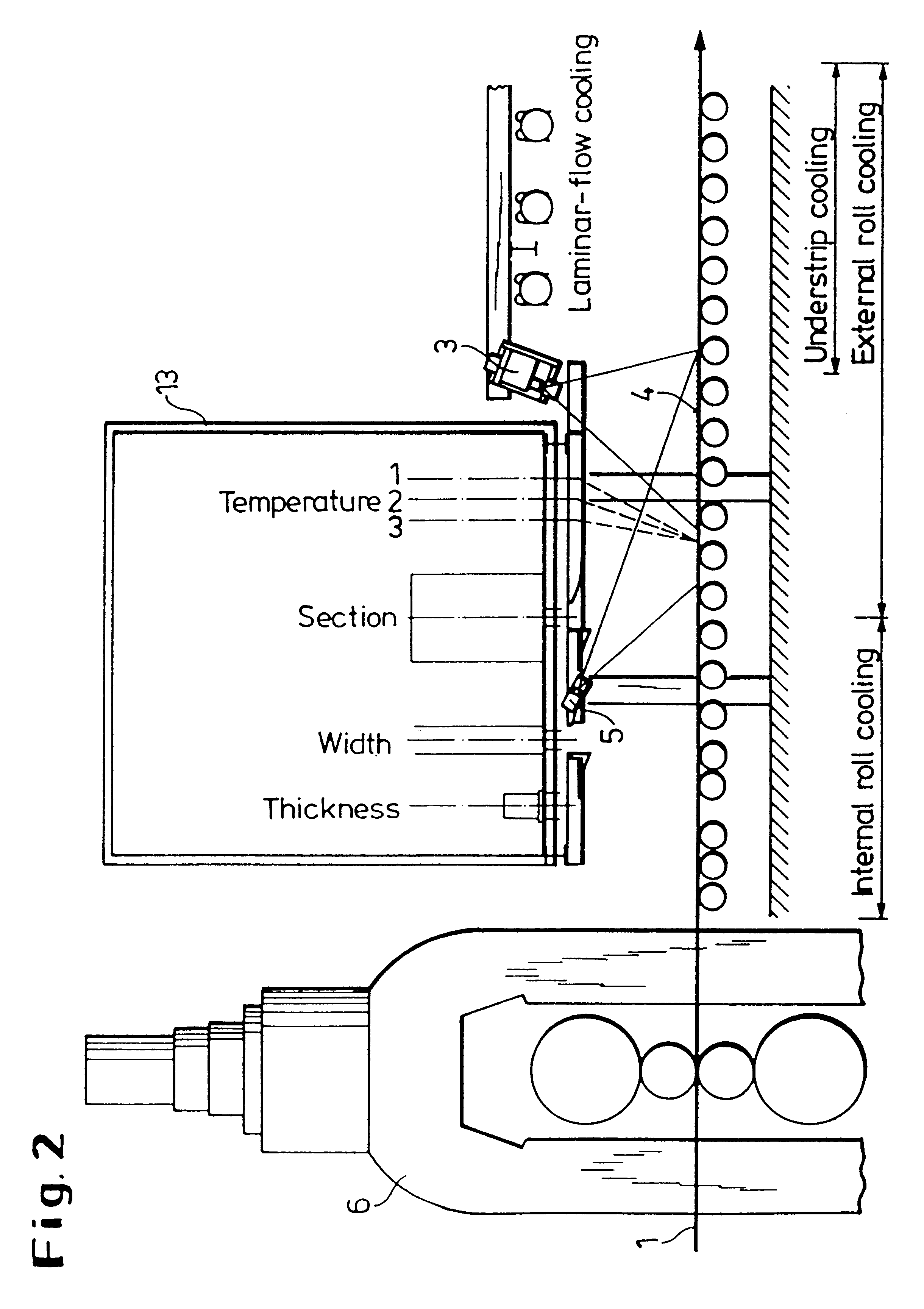
The measuring arrangement is disposed in one case in the run-out from the finishing stands 6 and in the other case before the coiler 7, on an instrument case 13. The CCD camera 5 is located on the side of the instrument case nearer to the coiler 7, in a water-cooled housing. The projector 3 is located on the side of the instrument case remote from the coiler 7. To remove heat the housing is cooled with air. The cooling of the projector 3 and of the camera 5 is necessary to remove their intrinsic heat and the radiant heat from the strip 1, which is at about 1000.degree. C.

The camera 5 and the projector 3 are arranged in succession relative to the direction of travel of the strip and are aimed at a region of the strip located between them, on which the line pattern is produced and sampled. The projector used may, for example, be a xenon light source, which produ...


PUM

PropertyMeasurementUnit
temperatureaaaaaaaaaa
finishing speedsaaaaaaaaaa
flatnessaaaaaaaaaa

Abstract

The invention relates to a flatness measurement and control system for metal strip, which makes it possible to obtain improved strip or coil quality by a simple and effective measurement of departures from flatness and to control the finishing parameters through the evaluation of a line pattern on the strip surface or on the end face of a coil as it is coiled.

Description

The invention relates to a flatness measurement and control system for metal strip and for the end faces of the coil when coiling strip.BACKGROUND AND PRIOR ARTThe contact measurement usually used in cold strip mills is only possible in the hot strip field at the expense of substantial outlay on maintenance, because of the high strip temperature of from about 1000.degree. C. Contact measurement on the end faces of a coil being formed in a coiler is also not possible. It is therefore difficult, if not completely impossible, to coil strip in such a way that in the coil every turn lies exactly over the preceding one so that flat end faces are obtained. And even in cold strip mills efforts are made to avoid contact measurement, since the mechanical measuring elements have only a limited life.Strip flatness is therefore preferably measured without contact. For example, it is known to measure departures from flatness by means of spots of light projected on to the strip. The position in sp...

Claims


Application Information

Patent Timeline
Patent Type & Authority Patents(United States)
IPC IPC(8): B21B37/28B21B37/42B21B38/00B21B37/44B21B38/02G01B11/30B21B37/74B21B37/48B21B37/76B21B45/02B21B37/54B21B38/04B21C51/00
CPCB21B37/42B21B37/44G01B11/306B21B38/02B21B37/54B21B37/76B21B38/04B21B45/0218B21B38/006
Inventor MULLER, ULRICHPEUKER, GUSTAVSONNENSCHEIN, DETLEFWINTER, DETLEFDEGNER, MICHAELTHIEMANN, GERD
Owner THYSSEN KRUPP STAHL AG
Why Eureka
Try Eureka