Mirror having an illuminated film for signaling and general illumination

Inactive Publication Date: 2001-09-11
MACHER DAVID +1
View PDF21 Cites 37 Cited by
  • Summary
  • Abstract
  • Description
  • Claims
  • Application Information

AI Technical Summary

Problems solved by technology

A disadvantage in this respect is the rather low light intensity in such films according to present prior art, which at present comes to about 200 Candela/m.sup.2, and the low durability of the films, so that failures frequently occur.
Such assembly channels also incur high costs in m

Method used


Image

  • Mirror having an illuminated film for signaling and general illumination
  • Mirror having an illuminated film for signaling and general illumination
  • Mirror having an illuminated film for signaling and general illumination

Examples


Embodiment Construction

It should initially be stated that in the variously described embodiments, identical parts have been provided with identical reference numerals or identical component titles, the disclosures contained in the entire description being logically transferable to identical parts with identical reference numerals or identical component titles. In addition, the details of position selected in the description, such for example as top, bottom, lateral, etc. refer to the FIG. directly described or illustrated, and upon an alteration in position are to be logically transferred to the new position. Furthermore, individual features from the various embodiments shown can represent independent solutions according to the invention.

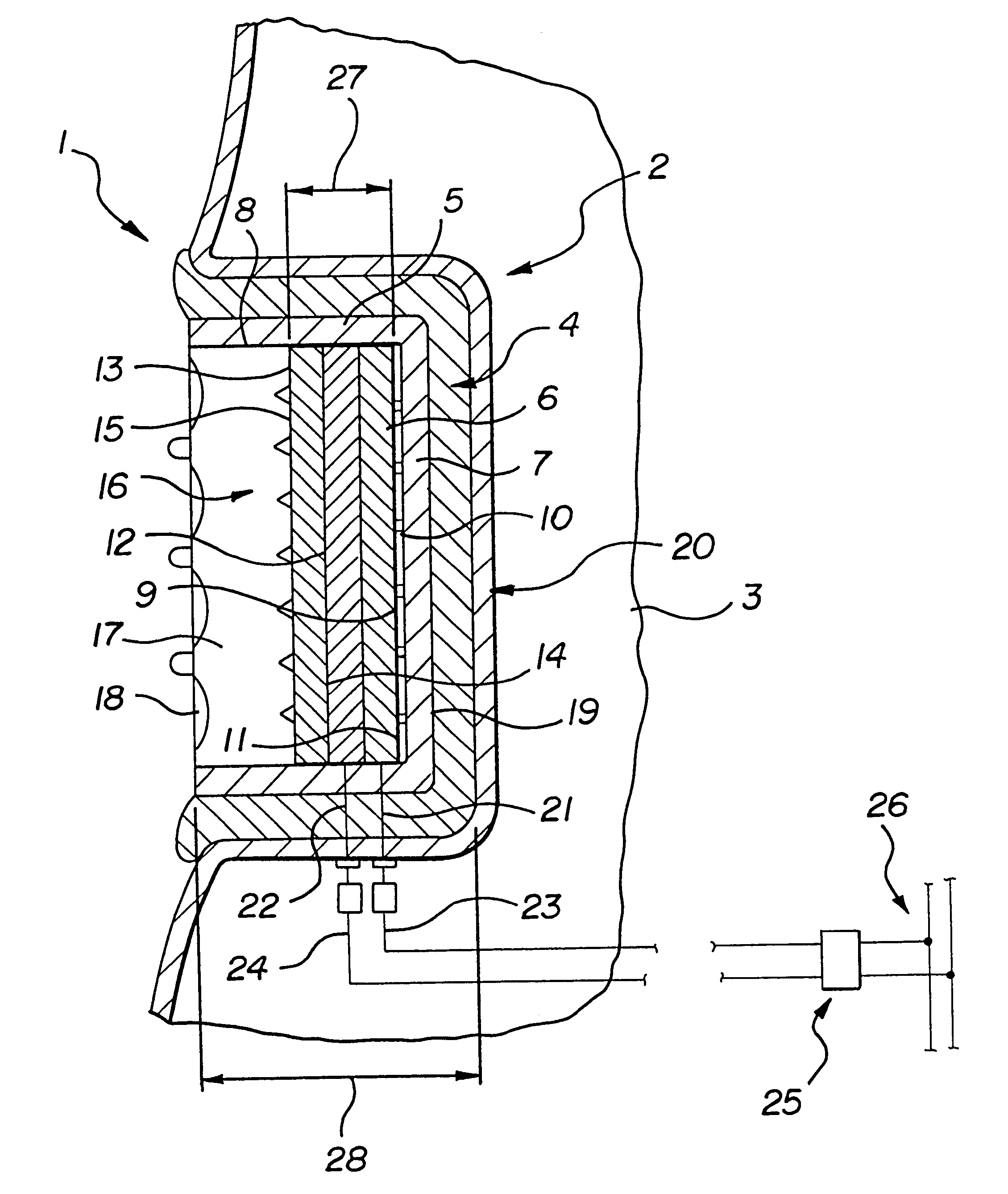
In FIG. 1, a lighting device 1 is shown inserted in a receiving means 2 of a casing portion 3. The lighting device 1 substantially consists of a lighting element 4, which consists of an at least double-layered electro-luminescent film 5 and is connected over the entire su...


PUM


Abstract

An external mirror assembly for an automotive vehicle has a shell having an aperture. A mirror is carried by the shell, substantially occluding the aperture. The mirror assembly has a lighting element having an electroluminescent film electrically connected to a triggering device for energizing the film and illuminating the mirror assembly. The triggering device includes first and second switches for generating a series of high and low frequency pulses and a control device connected to each of the switch for triggering each of the switches to illuminate the lighting element in either a flashing or continuous pattern.

Description

1. Field of the InventionThe invention relates to a lighting device.2. The Prior ArtSuch a lighting device is known as a flexible, self-adhesive film brake light for motor vehicles according to DE 297 06 601 U1. This consists of a thin flexible film which is intensely illuminative and reflective, can be attached in a self-adhesive manner to the rear or rear window of the motor vehicle, and is supplied via a transformer with voltage through cable connections and connection to a brake light cable. A disadvantage in this respect is the rather low light intensity in such films according to present prior art, which at present comes to about 200 Candela / m.sup.2, and the low durability of the films, so that failures frequently occur.The object of the invention is now to provide a lighting element in which the light intensity is considerably increased, and whose structure offers the greatest possible protection against mechanical damage.The object of the invention is achieved by the lightin...

Claims


Application Information

Patent Timeline
IPC IPC(8): B60Q3/00B60Q3/02B60Q1/26B60R1/12H05B33/12G09F13/22
CPCB60Q1/2665B60Q3/0226H05B33/12B60R1/1207G09F2013/227B60Q2400/10B60Q3/252
Inventor MACHER, DAVIDZORN, HEINZ
Owner MACHER DAVID
Why Eureka
Try Eureka