Broadband low-sidelobe series-fed CTS (Continuous Transverse Stub) antenna

A low-sidelobe antenna technology, applied in the field of series-fed continuous-section segment array antenna CTS antenna, can solve the problems of low-sidelobe antennas with narrow bandwidth, large volume, and high profile, and achieve the effects of low cost, small volume, and low profile

Inactive Publication Date: 2017-11-07
10TH RES INST OF CETC
View PDF5 Cites 10 Cited by
  • Summary
  • Abstract
  • Description
  • Claims
  • Application Information

AI Technical Summary

Problems solved by technology

[0007] The purpose of the present invention aims at the deficiencies of the prior art, as well as defects such as narrow bandwidth or high profile and large volume of existing low-sidelobe antennas, to pr

Method used


Image

  • Broadband low-sidelobe series-fed CTS (Continuous Transverse Stub) antenna
  • Broadband low-sidelobe series-fed CTS (Continuous Transverse Stub) antenna
  • Broadband low-sidelobe series-fed CTS (Continuous Transverse Stub) antenna

Examples


Embodiment Construction

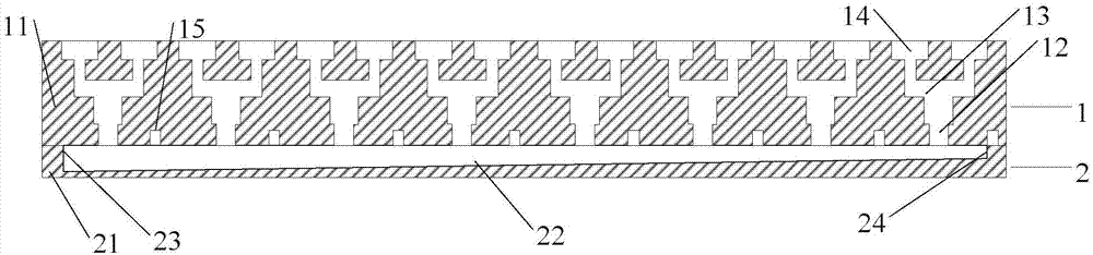
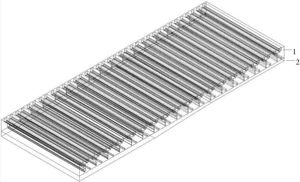
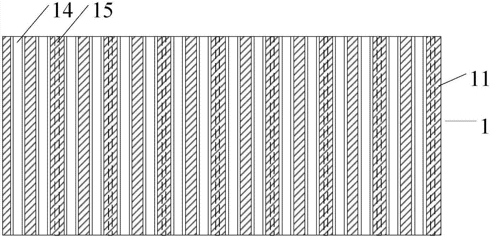
[0020] refer to Figure 1-Figure 4 . In the example described below, the broadband low-sidelobe series-fed CTS antenna includes an upper radiation array 1 placed above the lower feeding waveguide cavity 2, a radiation array 1 with several air slots and a feeding waveguide cavity 2. The metal part of the radiation array 1 is the metal wall 11, and the feeding waveguide cavity 2 is the feeding network of the antenna. It is characterized in that: the radiation array 1 has several hollowed-out air long slots 12, and the air long slots 12 are Two-stage stepped transition structure, these long air slots 12 are arranged at equal intervals, and a waveguide power divider 13 divided into two is arranged above the boundary step surface, and the waveguide power divider 13 divides the air long slots 12 into two identical two-stage The ladder transition channel 14; the long air slot 12, the waveguide power divider 13 and the two-stage ladder transition channel 14 together form the radiatio...


PUM


Abstract

The invention provides a broadband low-sidelobe series-fed CTS (Continuous Transverse Stub) antenna, and aims to provide a CTS antenna which is high in gain and efficiency, good in standing wave, high in radiation capability and obvious in grating lobe suppressing effect. The broadband low-sidelobe series-fed CTS antenna is implemented according to the technical scheme that a radiation array (1) is provided with a plurality of hollowed-out air elongated slots (12) with a two-stage stepped transition structure, a split waveguide power divider (13) is arranged above a boundary step surface, and each waveguide power divider divides the corresponding air elongated slot into two identical two-stage stepped transition channels (14); and in operation, a feed waveguide cavity (2) at the bottom of the radiation array provides quasi-TEM waves through a hollowed-out inclined air cavity (22), and the quasi-TEM waves sequentially flow into each antenna radiation unit in the radiation array (1) from left to right and radiate into the natural space from the air elongated slot to the waveguide power divider and then to the two-stage stepped transition channels, thereby enabling an antenna directional pattern to realize low sidelobe within a broadband along a radiation unit distribution surface. The antenna provided by the invention is particularly suitable for acting as a broadband low-sidelobe series-fed array antenna.

Description

technical field [0001] The invention relates to a series-fed continuous section segment array antenna CTS (Continuous Transverse StubArrays) antenna, especially a series-fed array antenna suitable for broadband, low sidelobe, low profile, low cost and high performance. Background technique [0002] With the rapid development of modern wireless communication technology, low-profile waveguide slot antennas are increasingly favored by people because of their advantages such as light weight, low cost, and easy processing. However, the general waveguide slot antenna has a narrow bandwidth, and the sidelobe increases with the frequency shift, so it is limited in practical applications. Therefore, how to widen the bandwidth of the low-profile waveguide slot antenna and achieve low sidelobes in the pattern is of great significance. As a kind of waveguide slot antenna, the CTS antenna adopts a continuous transverse slot as the radiation unit, and the antenna bandwidth can be expande...

Claims


Application Information

Patent Timeline
IPC IPC(8): H01Q21/12H01Q1/36
Inventor 刘熠志刘小亮
Owner 10TH RES INST OF CETC
Why Eureka
Try Eureka