
Deflection current/high voltage integration type power supply

a technology of high voltage and power supply, applied in the field of power supply, can solve the problems of large number of total elements, and affecting the current of the current,

Inactive Publication Date: 2001-09-11
MURATA MFG CO LTD
View PDF15 Cites 12 Cited by
  • Summary
  • Abstract
  • Description
  • Claims
  • Application Information

AI Technical Summary

Benefits of technology

According to the present invention, both the deflection current and the high voltage at the secondary winding of the flyback transformer can be independently controlled by the on-timing / off-timing of the second switching element to control the primary input voltage (+B) of the flyback transformer, and the number of elements is not increased, or the responsiveness in controlling the high output voltage and the deflection current is not degraded because no smoothing circuit is connected to the +B control part or the deflection current control part.

Problems solved by technology

However, the deflection current is affected and fluctuates due to the control for stabilization of the high voltage when the high voltage load changes.
However, in the power supply device of the diode modulator circuit system, there is a problem that a switch element for controlling the voltage +B mentioned above and an element for controlling the deflection current are also required in addition to a main switch element to connect / disconnect the primary current in the flyback transformer, and the number of total elements becomes large, and the circuit becomes complex.
Further, there is a problem in that the responsiveness in stabilization of the high output voltage and stabilization of the deflection current deteriorate because smoothing circuits are interposed at the +B control part and the deflection current control part.

Method used


Image

  • Deflection current/high voltage integration type power supply
  • Deflection current/high voltage integration type power supply
  • Deflection current/high voltage integration type power supply

Examples


first embodiment

a deflection current / high voltage integration type power supply of the present invention is described referring to FIGS. 1A, 1B, 2A, 2B, 3A, 3B, 4 to 5, 6A and 6B.

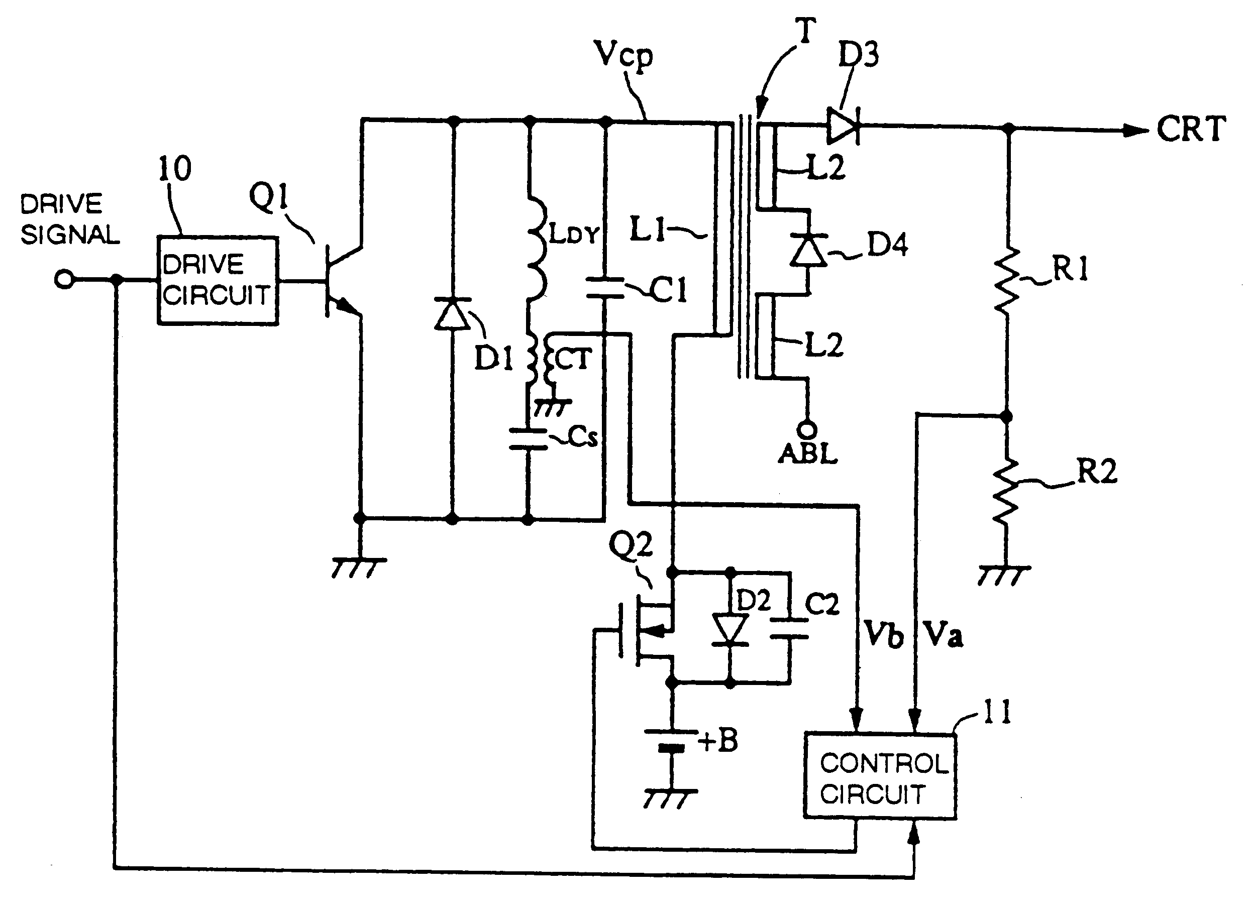
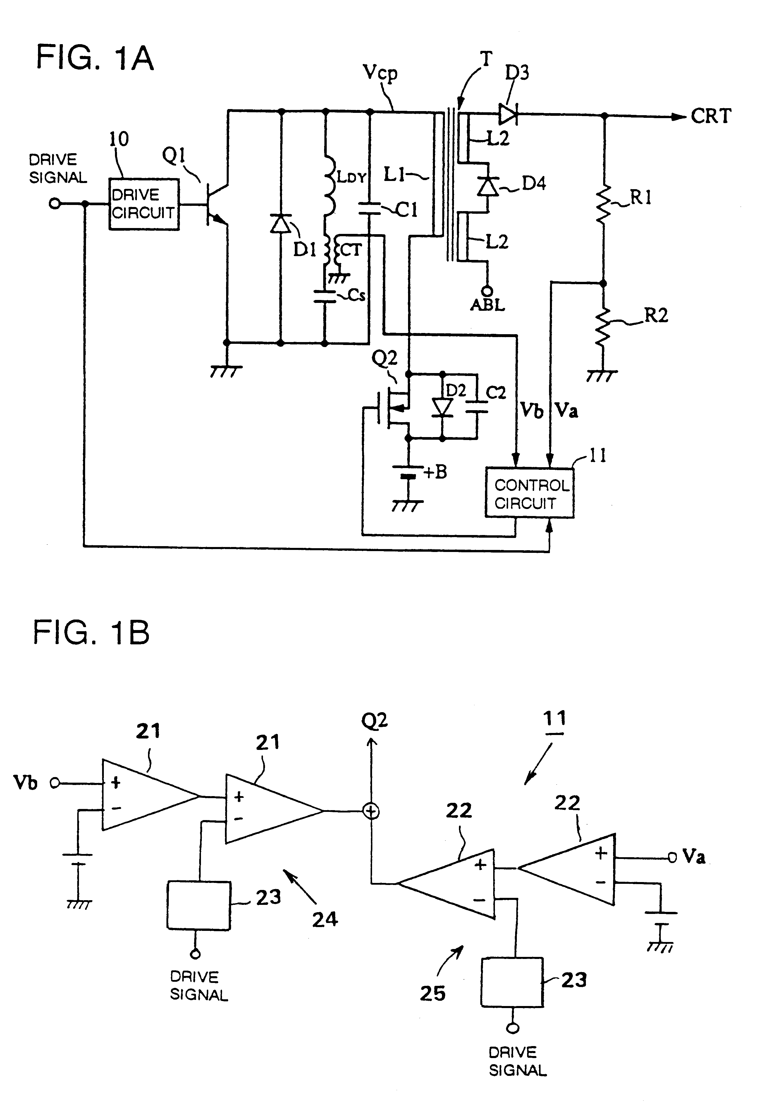
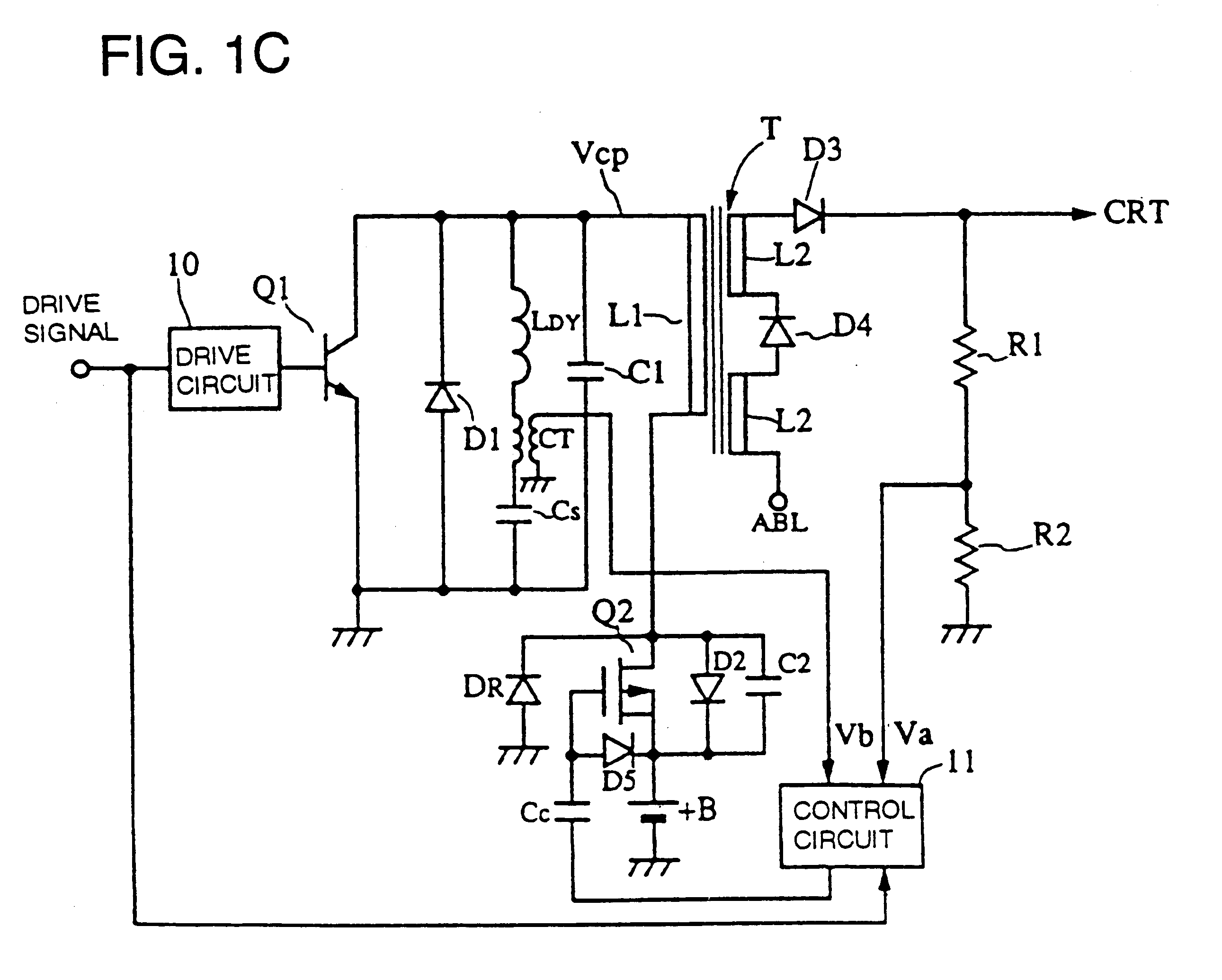
FIG. 1A shows an example of the first embodiment. As shown in FIG. 1A, the deflection current / high voltage integration type power supply comprises a flyback transformer T having a primary winding L1 and a secondary winding L2. A series circuit comprising a deflection coil L.sub.DY, a current transformer CT and a capacitor C.sub.S is connected to the primary winding L1 of the flyback transformer T, and a damper diode D1 and a switch element Q1 are respectively connected in parallel to the series circuit of the deflection coil L.sub.DY and the capacitor C.sub.S. In addition, a resonance capacitor C1 is connected in parallel to the series circuit of the deflection coil L.sub.DY and the capacitor C.sub.S. Note that the actual capacitance of the resonance capacitor is the combined amount of a distributed capacitance of the whol...


PUM


Abstract

A deflection current / high voltage integration type power supply has a flyback transformer having a primary winding and a secondary winding; a series circuit of a deflection coil and a first capacitor, connected in series to the primary winding of the flyback transformer; a resonance capacitor connected in parallel to the series circuit of the deflection coil and the first capacitor; a first switching element, connected in parallel with the series circuit of the deflection coil and the first capacitor, to be turned on / turned off by a drive signal so that a high voltage is generated at the secondary winding of the flyback transformer and a deflection current flows in the deflection coil; a parallel connection circuit of a second switching element and a second capacitor, connected in series to the primary winding of the flyback transformer; and a switching control means to control the deflection current flowing in the deflection coil and the high voltage generated at the secondary winding of the flyback transformer by controlling the on-timing and the off-timing of the second switching element in approximate synchronism with the drive signal.

Description

1. Field of the InventionThe present invention relates to a power supply for applying a high voltage and a deflection current to a cathode ray tube (CRT), etc.2. Description of the Related ArtA high-voltage generation circuit using a flyback transformer has been employed in a power supply for a CRT. The high-voltage generation circuit using the flyback transformer supplies the anode voltage to an anode of the CRT and a deflection current to a deflection yoke of the CRT. A power supply enabling these two roles by a single flyback transformer is referred to as a deflection current / high voltage integration type power supply.Conventionally, CRT displays for computers are required to display a highly precise image. Therefore, a deflection current / high voltage separation type power supply including a circuit part for generating a deflection current and a circuit part for generating a high voltage separately has been generally used. However, there arises a demand for a deflection current / h...

Claims


Application Information

Patent Timeline
IPC IPC(8): H04N3/18H04N3/185H01F38/42
CPCH04N3/185H04N3/19
Inventor IMAMURA, NOBUAKITAKAHASHI, HARUO
Owner MURATA MFG CO LTD
Learn More