Multichannel television sound stereo and surround sound encoder suitable for use with video signals encoded in plural formats

a multi-channel television and encoder technology, applied in the field of encoders for transmitting, can solve the problems of unauthorized copies of movies made on video cassette recorders (or "vcrs"), the quality of unauthorized copies made on video cassette recorders could be substantially reduced, and most devices used today to deliver audio information to a television are unable to successfully transmit surround sound information contained in the l-r band to the television

Inactive Publication Date: 2001-09-11
CE LABS LLC
View PDF21 Cites 15 Cited by
  • Summary
  • Abstract
  • Description
  • Claims
  • Application Information

AI Technical Summary

Problems solved by technology

Due to signal attenuation and noise considerations, most devices used today to deliver audio information to a television are unable to successfully transmit the surround sound information contained in the L-R band to the television.
However, because the DVD player produces video images of very high quality, the motion picture industry has long expressed concern that DVD players could be used to produce unauthorized copies of movies of quality comparable to the originals.
However, they cause unauthorized copies mad

Method used


Image

  • Multichannel television sound stereo and surround sound encoder suitable for use with video signals encoded in plural formats
  • Multichannel television sound stereo and surround sound encoder suitable for use with video signals encoded in plural formats
  • Multichannel television sound stereo and surround sound encoder suitable for use with video signals encoded in plural formats

Examples


Embodiment Construction

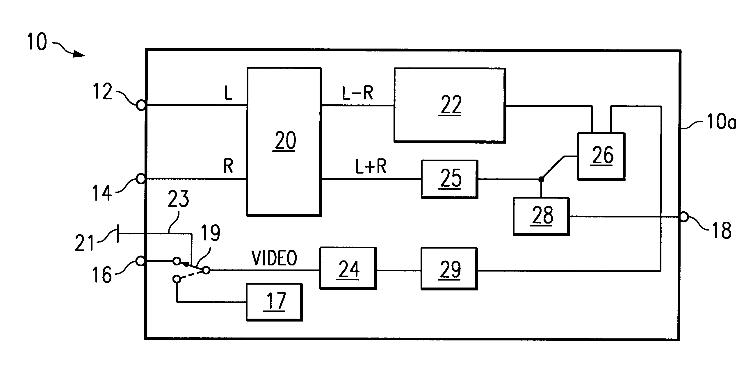
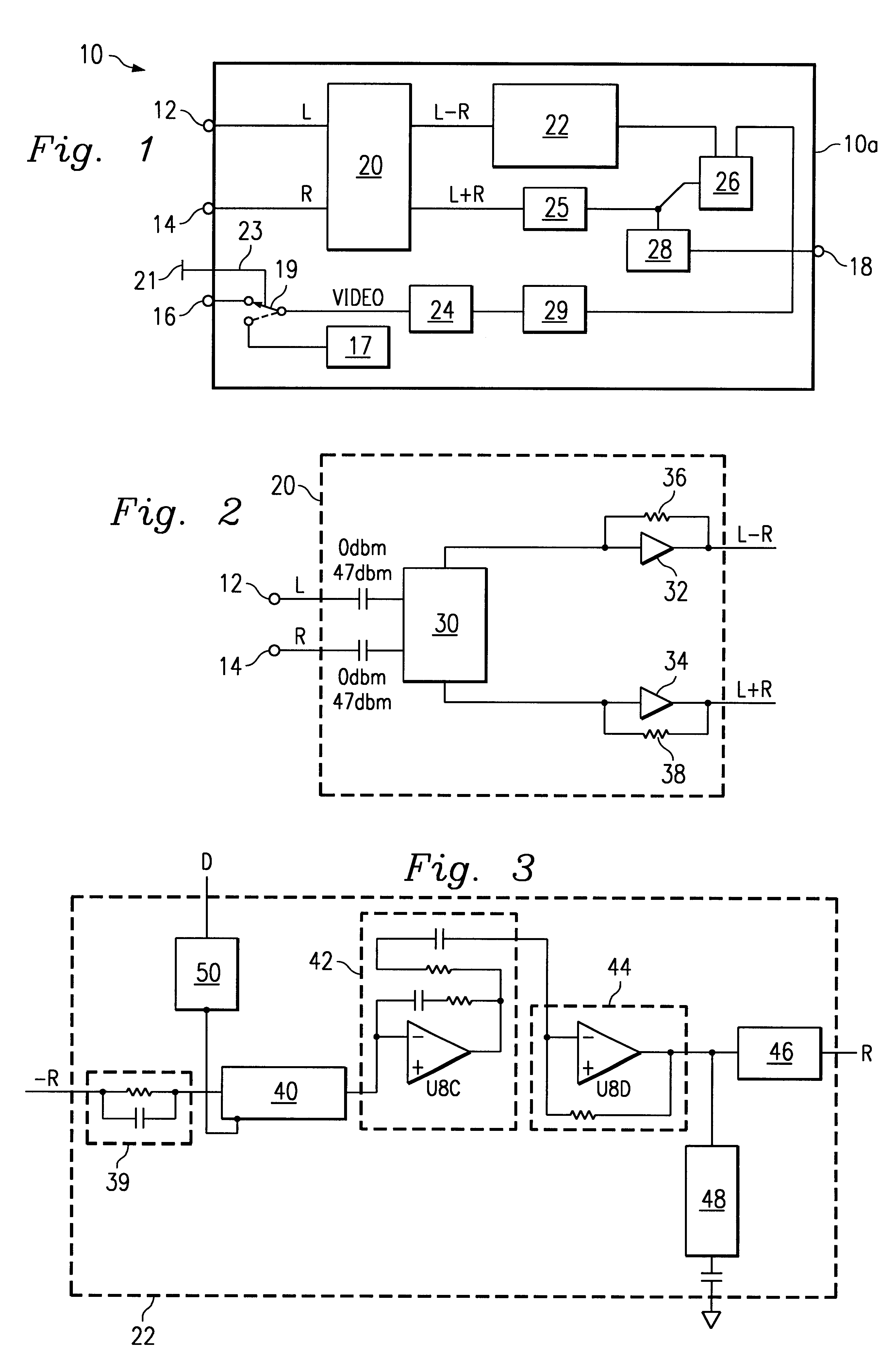
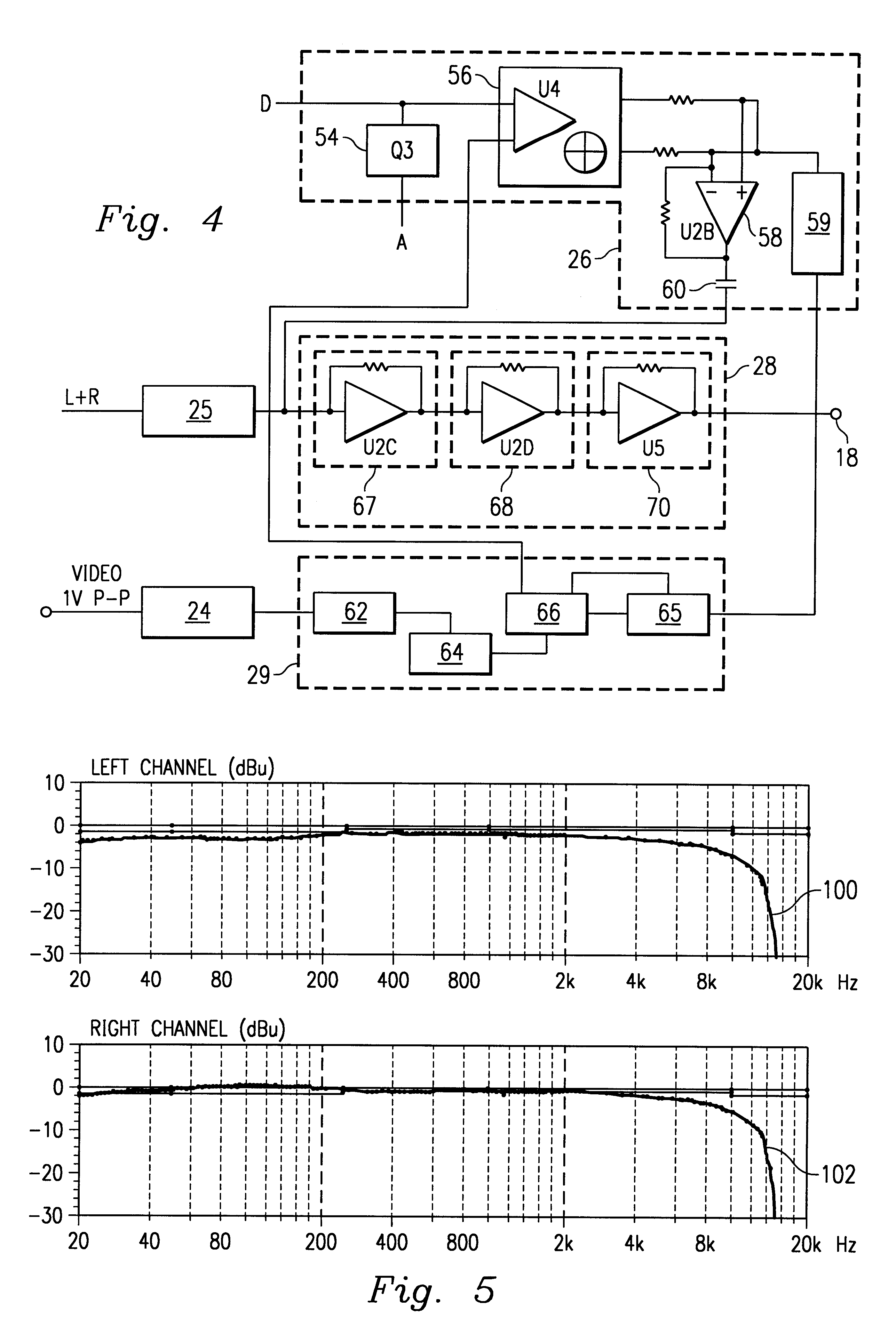
Referring first to FIG. 1, a MTS stereo / surround sound encoder 10 constructed in accordance with the teachings of the present invention will now be described in greater detail. The encoder 10 includes a protective housing 10a within which plural electronic components are housed. For example, the electronic components of the encoder 10 may reside on a printed circuit board (or "PCB") supportably mounted in the interior of the housing 10a. External connections, for example, plug connectors, supportably mounted in apertures formed in the housing 10a, which enable external coupling to various ones of the internally housed electronic components of the encoder 10 include a left audio input 12, a right audio input 14, a video input 16 and an audio output 18.

The electronic components of the encoder 10 which reside on the PCB supportably mounted within the housing 10a include an audio breakout matrix (or "ABM") 20, a surround sound conditioner (or "SSC") 22, a video stripper matrix (or "VSM"...


PUM


Abstract

Method and apparatus for generating a composite audio signal clocked to a selected frequency from left and audio input signals. A video/audio signal generator transmits the left and right audio input signals, together with a video signal having a horizontal synchronization signal embedded therein. If copy protection has not been applied to the video signal, the embedded horizontal synchronization signal will have a frequency of 15.734 KHz. If applied to the video signal, copy protection techniques will shift the frequency of the horizontal synchronization signal. To avoid distortion of the composite audio signal, a switch configured to selectively couple the video signal or a secondary video signal generated by an internal video signal generator to an audio signal processor which generates the composite audio output signal from the left and right audio input signals. Embedded within the secondary video signal is a horizontal synchronization signal having a frequency of 15.734 KHz. Thus, if copy protection features cause the frequency of the signal embedded within the primary video signal to shift, the switch may be used to couple the audio signal processor to the internal video signal generator, thereby ensuring that the composite audio signal will always be clocked to the selected frequency.

Description

1. Field of the InventionThe invention generally relates to encoders for transmitting audio information formatted in accordance with the multichannel television sound (or "MTS") standard in "surround sound" and, more particularly, relates to encoders for "surround sound" transmission of modified MTS formatted audio information.2. Description of Related ArtThe MTS standard governs the transmission of audio information to televisions. In accordance with this standard, audio information is carried in two signals, the L-R signal and the L+R signal. The L-R signal, which represents the difference between left (or "L") and right (or "R") channels, carries stereo information within a first frequency band and surround sound information within a second, higher, frequency band. Due to signal attenuation and noise considerations, most devices used today to deliver audio information to a television are unable to successfully transmit the surround sound information contained in the L-R band to t...

Claims


Application Information

Patent Timeline
IPC IPC(8): G11B27/28G11B27/10H04H9/00H04N5/14H04H1/00H04H20/47H04H60/31
CPCG11B27/105G11B27/28H04H20/47H04H20/89H04S3/00H04N5/602H04N5/607H04N7/06H04R5/04G11B2220/2562H04N5/913H04N5/147
Inventor AVALOS, SEALTIELKAYLOR, ROBERT D.KESSLER, ROBERT F.
Owner CE LABS LLC
Why Eureka
Try Eureka