On-board reductant delivery system

a reductant and delivery system technology, applied in the direction of machines/engines, positive displacement liquid engines, separation processes, etc., can solve the problems of low efficiency, low efficiency, cumbersome, cumbersome, etc., and achieve the effect of reducing the number of cylinders

Inactive Publication Date: 2001-09-25
FORD GLOBAL TECH LLC
View PDF23 Cites 118 Cited by
  • Summary
  • Abstract
  • Description
  • Claims
  • Application Information

AI Technical Summary

Problems solved by technology

In addition, the system must be compact, light-weight, cost and energy efficient.
However, these systems are

Method used


Image

  • On-board reductant delivery system
  • On-board reductant delivery system
  • On-board reductant delivery system

Examples


Embodiment Construction

)

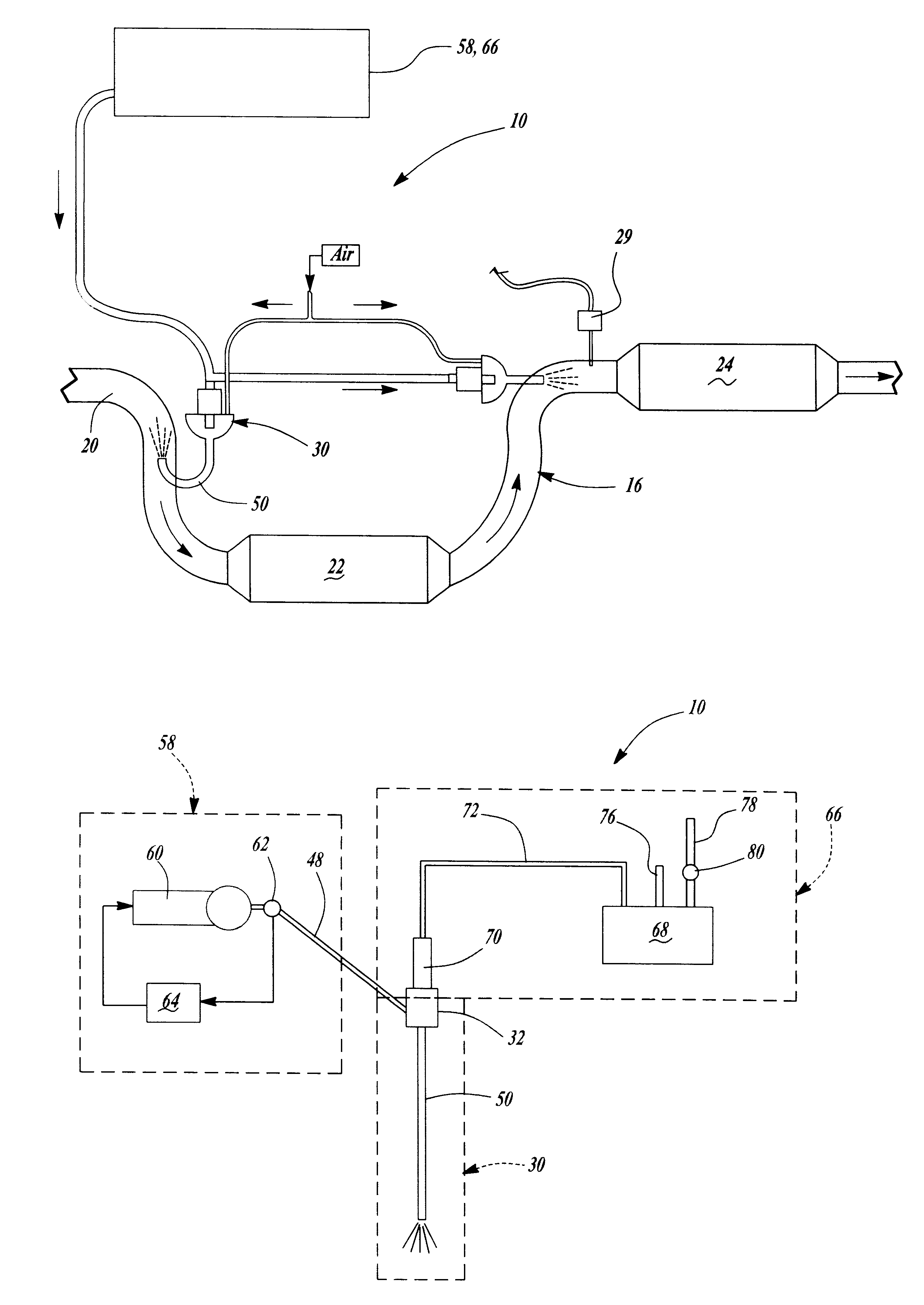
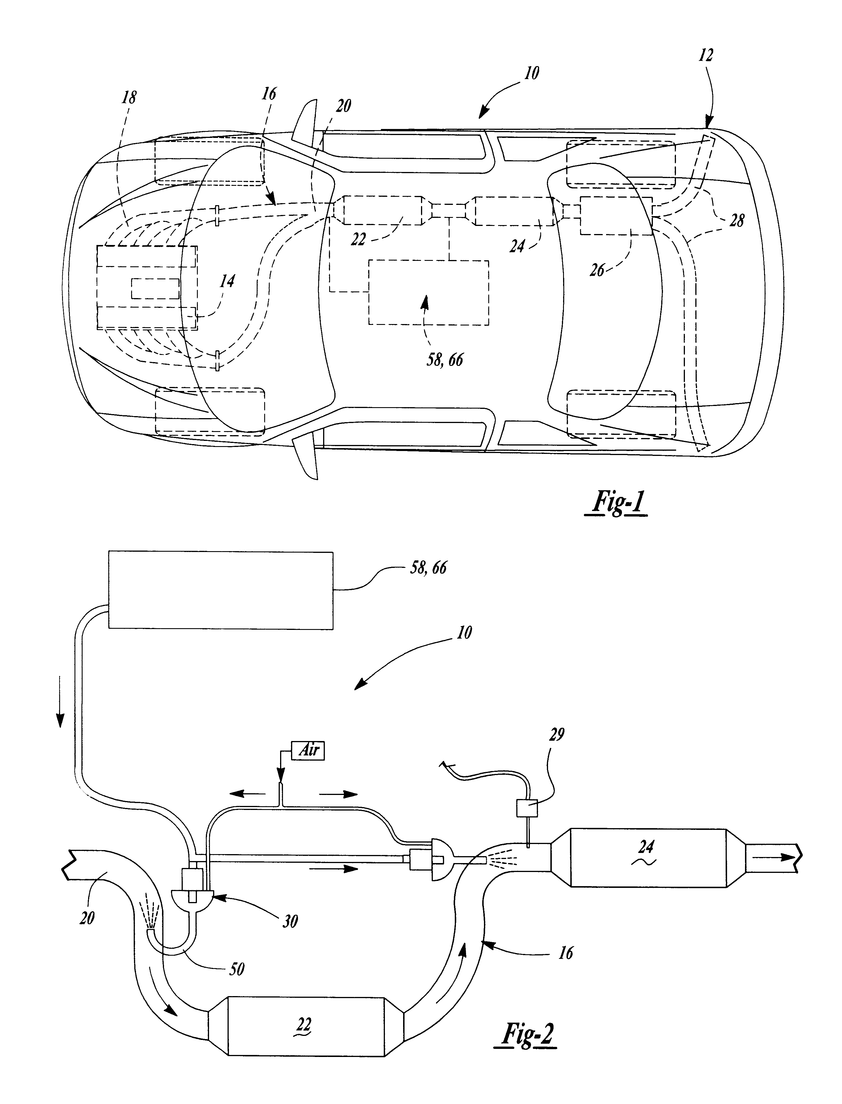
Referring to the drawings and in particular FIGS. 1 and 2, one embodiment of an on-board reductant delivery system 10, according to the present invention, is illustrated in operational relationship with a motor vehicle, generally indicated at 12. The motor vehicle 12 includes an engine 14 and an exhaust system, generally indicated at 16, connected to the engine 14. The exhaust system 16 includes an exhaust manifold 18 connected to the engine 14 and an exhaust pipe 20 extending from the exhaust manifold 18. The exhaust system 16 also includes at least one catalyst or catalytic converter, preferably a close coupled catalyst 22 and an underbody catalyst 24 connected to the exhaust pipe 20. The exhaust system 16 further includes a muffler 26 and tail pipe 28 extending from the underbody catalyst 24. The exhaust system 16 also includes an exhaust gas temperature sensor 29 connected to a controller. It should be appreciated that, except for the on-board reductant delivery system 10, the ...


PUM


Abstract

An on-board reductant delivery system for a motor vehicle includes a mixer/nozzle system for connection to an exhaust system of a motor vehicle. The on-board reductant delivery system also includes a fluid metering system connected to the mixer/nozzle system for metering reductants to the mixer/nozzle system. The on-board reductant delivery system further includes an air supply system connected to the mixer/nozzle system for delivering pressurized air to the mixer/nozzle system. The mixer/nozzle system mixes the reductants and pressurized air and sprays the mixture in the exhaust system of the motor vehicle to reduce NOx.

Description

1. Field of the InventionThe present invention relates generally to exhaust systems for motor vehicles and, more specifically, to an on-board reductant delivery system for an exhaust system of a motor vehicle.2. Description of the Related ArtExhaust systems for motor vehicles are known. Typically, the exhaust system includes an exhaust manifold connected to an engine of the motor vehicle and a close coupled catalyst connected via an exhaust pipe to the exhaust manifold. The exhaust system also includes an underbody catalyst connected via the exhaust pipe to the close coupled catalyst and a tail pipe connected to the underbody catalyst.Lean NOx catalysts (LNC) and selective catalytic reduction catalysts (SCR) are known to reduce NOx emissions from diesel and lean-burn gasoline engines. In order to promote NOx reduction under oxidizing environments, certain reductants such as hydrocarbon (HC) fuels and / or urea solution or other ammonia (NH3) containing compounds must be added. To func...

Claims


Application Information

Patent Timeline
IPC IPC(8): B01D53/94F01N3/20F01N7/00F01N7/02F01N13/02
CPCB01D53/9431B01D53/9495F01N3/2066F01N13/009F01N13/0093F01N2610/02F01N2610/1453Y02T10/24F01N2610/08Y02A50/20Y02T10/12
Inventor WU, CHING-HSONGHAMMERLE, ROBERT HENRY
Owner FORD GLOBAL TECH LLC
Why Eureka
Try Eureka