
Multi-resolution graph-based clustering

a graph-based clustering and multi-resolution technology, applied in the field of geological study of earth formations, can solve problems such as poor performance of existing systems which are highly automated, problem assigning, and not normally cost-effective to identify facies using these methods

Inactive Publication Date: 2001-09-25
HALLIBURTON ENERGY SERVICES INC
View PDF2 Cites 144 Cited by
  • Summary
  • Abstract
  • Description
  • Claims
  • Application Information

AI Technical Summary

Problems solved by technology

It is not normally cost-effective to identify facies using these methods.
The most accurate existing systems and methods require a substantial amount of user participation to set up, and conversely, those existing systems which are highly automated tend to perform poorly.
In this approach, the geologist often has a problem assigning specific geological facies to the clusters, which tend to be much larger than the clusters in the previous approach.
A large number of clusters require much work by the geologist to match clusters to geology; too few clusters cause the geologist problems in making meaningful linkages between clusters and geology.
The electrofacies analysis systems described above suffer from various limitations and drawbacks.
This is a limitation because the results are very sensitive to this parameter.
Furthermore, unless the number is large, the identified clusters may have shapes that are not geologically meaningful.
On the other hand, manual merging of a large number of small clusters based on similar geological characteristics by hand makes this process slow and subjective.
Furthermore, because electrofacies analysis occurs in N-dimensional space it is still difficult even for a trained individual with good visualization tools to identify clusters manually.

Method used


Image

  • Multi-resolution graph-based clustering
  • Multi-resolution graph-based clustering
  • Multi-resolution graph-based clustering

Examples


Embodiment Construction

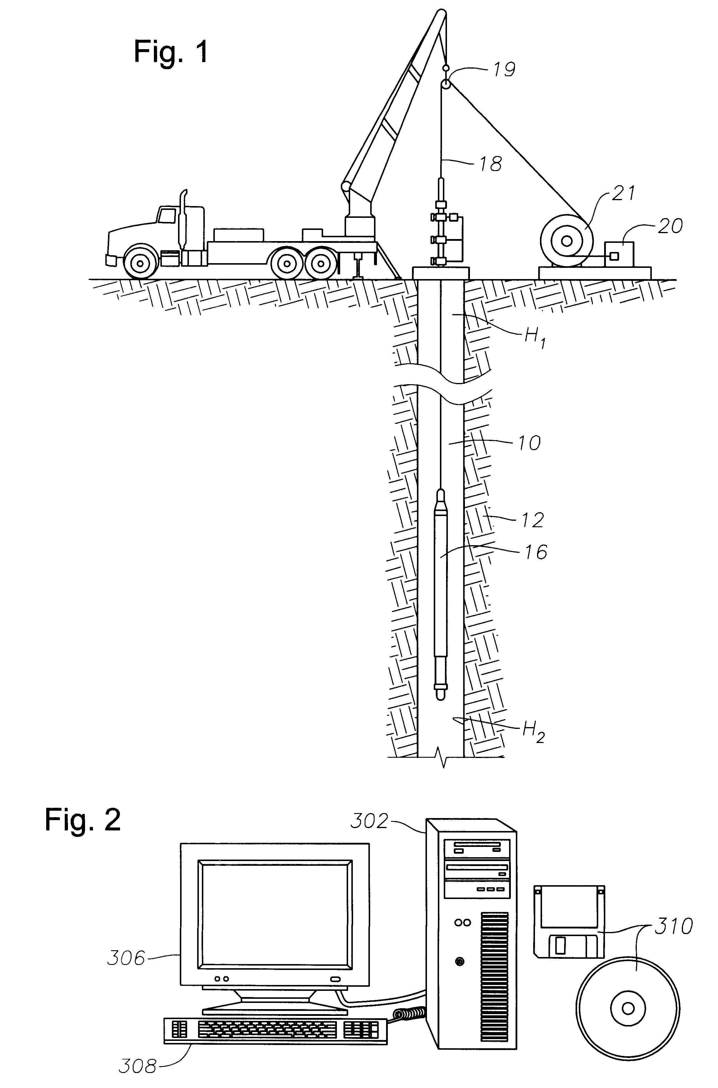
FIG. 1 shows logging equipment in a bore hole 10 going through earth formations 12. The equipment includes a sonde 16 is suspended in the bore hole 10 at the end of a cable 18. Cable 18 connects sonde 16 both mechanically and electrically, by means of a pulley 19 on the surface, to a control installation 20 equipped with a winch 21 around which the cable 18 is wound. The control installation includes recording and processing equipment known in the art that make it possible to produce graphic representations called logs of the measurements obtained by the sonde 16 according to the depth of the sonde in the bore hole or well 10.

The bore hole 10 passes through a series of earth formations (not specifically shown) that is typically composed of a series of zones or "beds". The zones are identified by the rock facies they contain, e.g. clay, limestone, etc. From the geological viewpoint, each of these successive zones is characterized by a relative homogeneity that is revealed by a set of...


PUM


Abstract

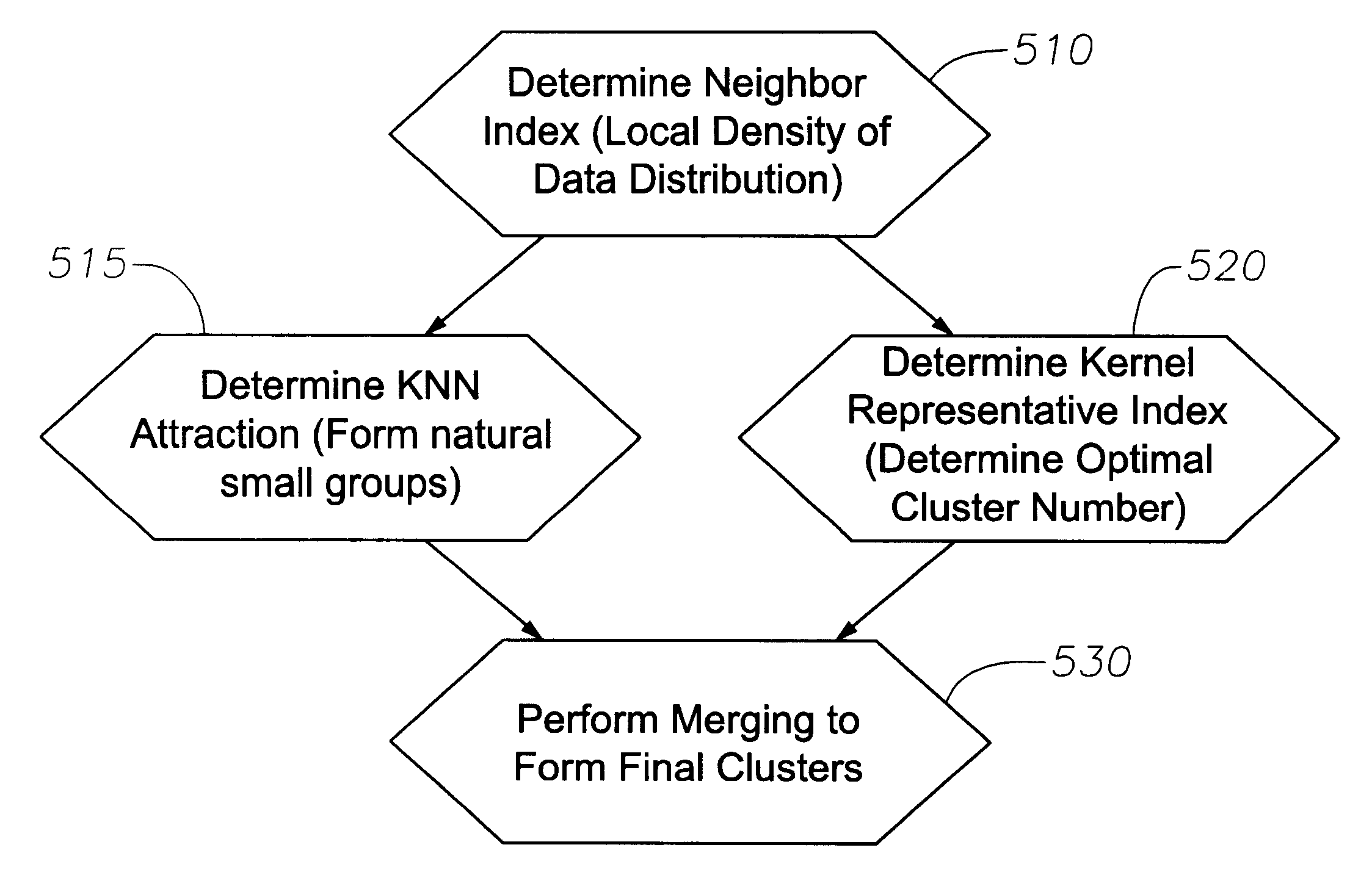
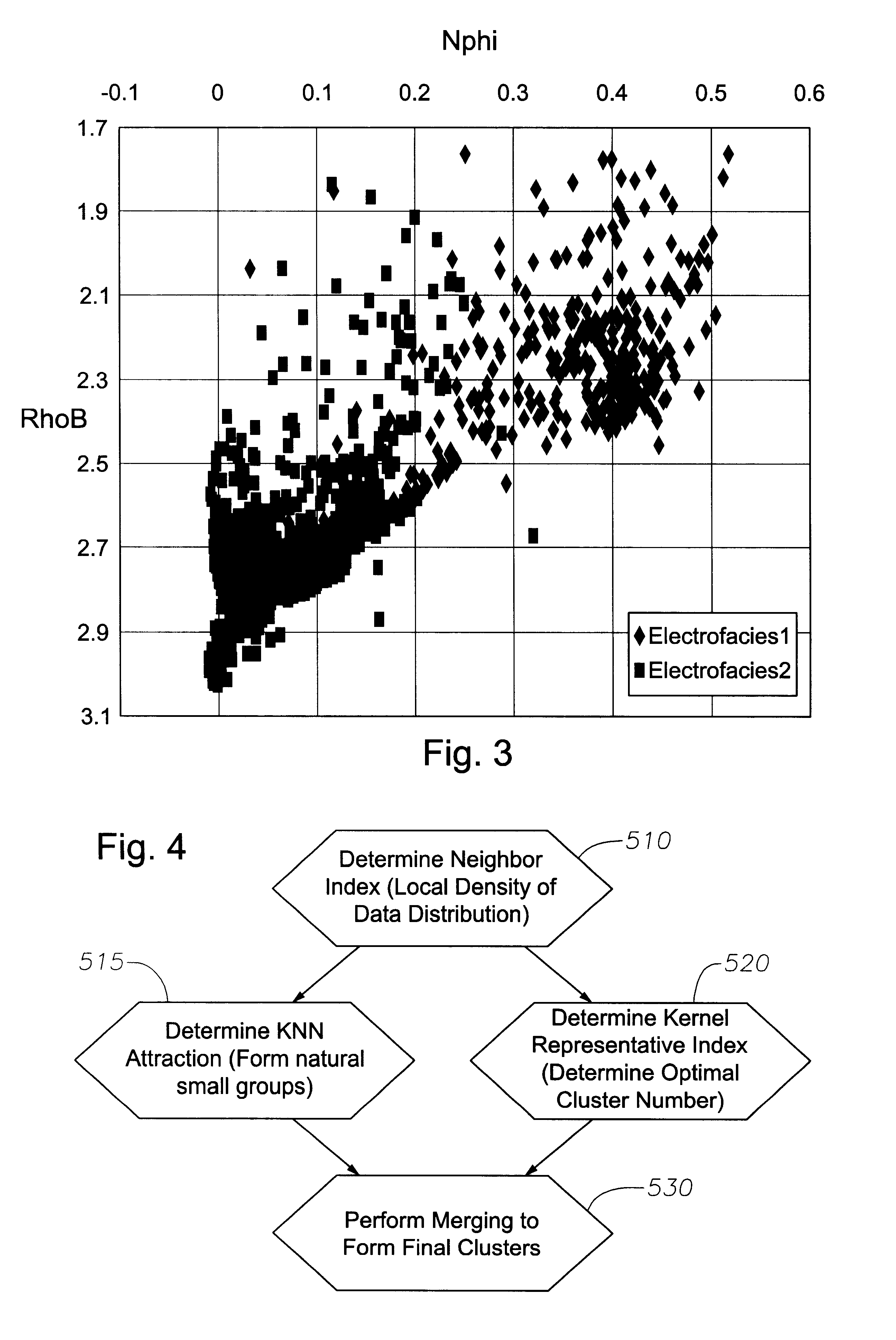
An apparatus and method for obtaining facies of geological formations for identifying mineral deposits is disclosed. Logging instruments are moved in a bore hole to produce log measurements at successive levels of the bore hole. The set of measurements at each such level of the bore hole interval is associated with reference sample points within a multidimensional space. The multidimensional scatter of sample points thus obtained is analyzed to determine a set of characteristic modes. The sample points associated with characteristic modes are grouped to identify clusters. A facies is designated for each of the clusters and a graphic representation of the succession of facies as a function of the depth is thus obtained. To identify the clusters, a "neighboring index" of each log measurement point in the data set is calculated. Next, small natural groups of points are formed based on the use of the neighboring index to determine a K-Nearest-Neighbor (KNN) attraction for each point. Independently of the natural group formation, an optimal number of clusters is calculated based on a Kernel Representative Index (KRI) and based on a user-specified resolution. Lastly, based on the data calculated from the prior steps, final clusters are formed by merging the smaller clusters.

Description

1. Field of the InventionThe present invention generally relates to the geological study of earth formations for the location and exploitation of mineral deposits using electrofacies analysis. More particularly, the present invention relates to a new system and method for identifying formations of mineral deposits using a user-friendly and reliable clustering technique that can extract natural clusters from sets of logged data points for improved electrofacies analysis of the formation.2. Description of the Related ArtMineral and hydrocarbon prospecting is based upon the geological study and observation of formations of the earth's crust. Correlations have long been established between geological phenomena and the formation of mineral and hydrocarbon deposits that are sufficiently dense to make their exploitation economically profitable.The study of rock and soil facies encountered while prospecting for minerals takes on particular importance. As used herein, a facies is an assembla...

Claims


Application Information

Patent Timeline
IPC IPC(8): G01V3/38
CPCG06K9/622G01V3/38
Inventor YE, SHIN-JURABILLER, PHILLIPE J. Y. M.
Owner HALLIBURTON ENERGY SERVICES INC
Learn More