
Mechanical safety device for a door pivotally mounted on a frame

a safety device and pivotal technology, applied in the direction of door/window fittings, hinges, building components, etc., can solve the problems of increasing the force required to move the door, presenting a large swelling in the open position of the door, and the risk of fingers getting jammed between the door and the support frame, etc., to achieve the effect of reliable safety device and easy fitting

Inactive Publication Date: 2001-10-09
DELEFOSSE BRUNO +2
View PDF19 Cites 42 Cited by
  • Summary
  • Abstract
  • Description
  • Claims
  • Application Information

AI Technical Summary

Benefits of technology

The object of the invention is to achieve a reliable safety device, able to be easily fitted to all types of hinged doors, not presenting any protruding part regardless of the angle of pivoting of the door, and enabling total protection to be achieved along the height of the door, and on both the apparent (i.e., where the hinges are visible when the door is closed) and non-apparent (i.e., where the hinges are not visible when the door is closed) sides of the hinges.
the strip and the plate extend right down to the bottom of the door to achieve total protection.
The coaxial arrangement of the tubular element with the hinges and the sliding movement of the flexible strip prevent any swelling effect when the door is opened. The tubular element has a diameter close to that of each hinge and is provided with a flat fixing tab, the assembly thus formed having the form of a profiled part made of rigid or flexible plastic material able to be assembled either to the frame or to the door.

Problems solved by technology

Risks of fingers getting jammed between the door and the support frame can occur on the side where the closing handle is situated, and on the side where the hinges are located as a result of deliberate or involuntary slamming of the door without the handle being used.
Such devices are described in the documents FR-A-2620484, 2565622, and 2646460, and present a large swelling in the open position of the door.
Such a swelling is unaesthetic and moreover increases the force required to move the door when deformation of the flap or gusset takes place.

Method used


Image

  • Mechanical safety device for a door pivotally mounted on a frame
  • Mechanical safety device for a door pivotally mounted on a frame
  • Mechanical safety device for a door pivotally mounted on a frame

Examples


Embodiment Construction

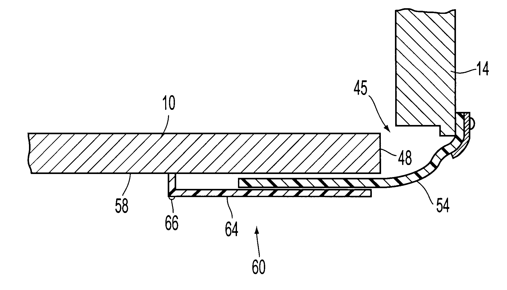
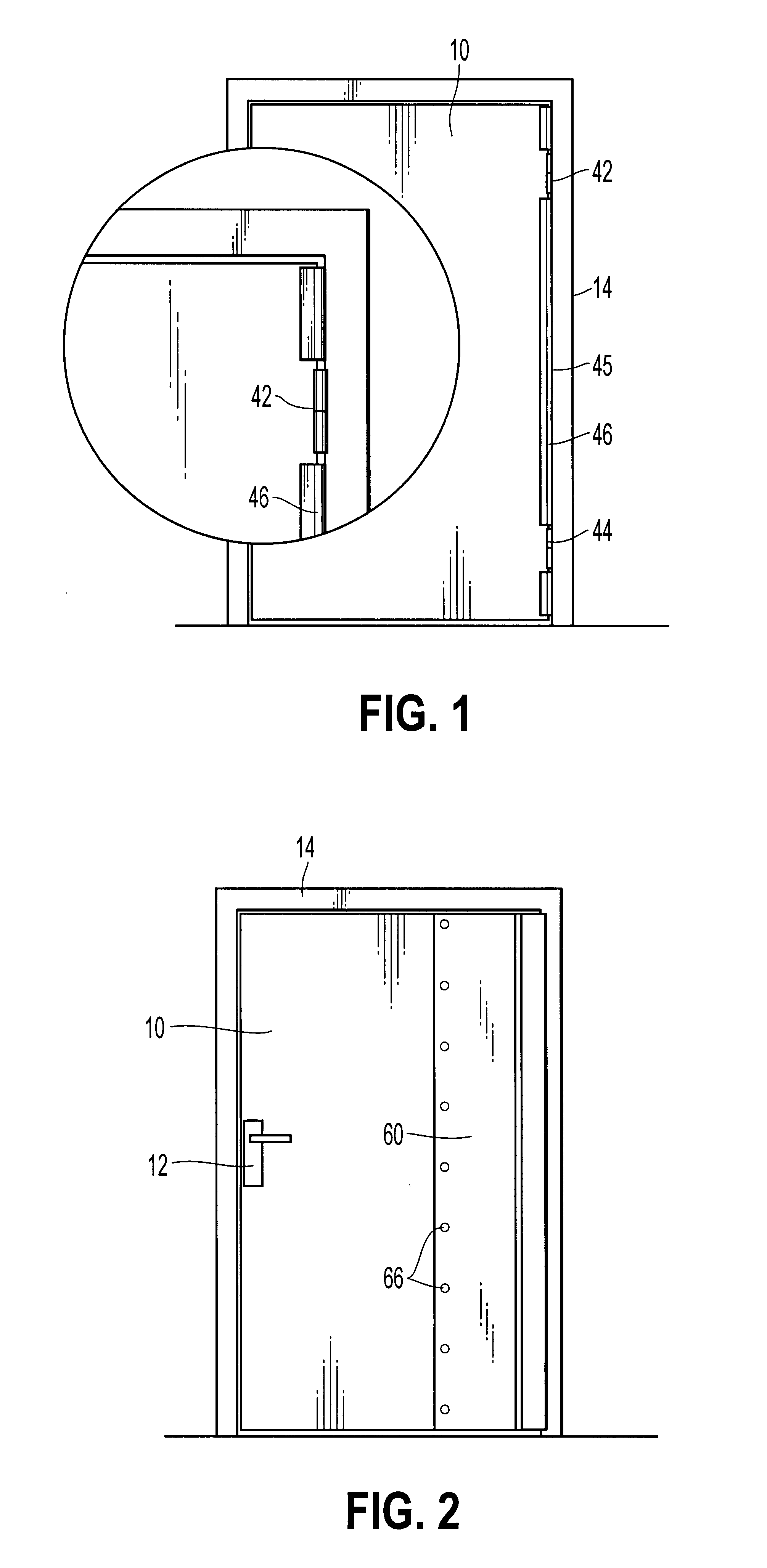
With reference to the figures, a door 10 with hinges 42, 44 comprises an actuating handle 12 and a protection unit 40 to prevent fingers from getting jammed when the door 10 is closed, by preventing access to the vertical gap 45 arranged on the side where the hinges 42, 44 are located between the frame 14 and the rear edge 48 of the door 10.

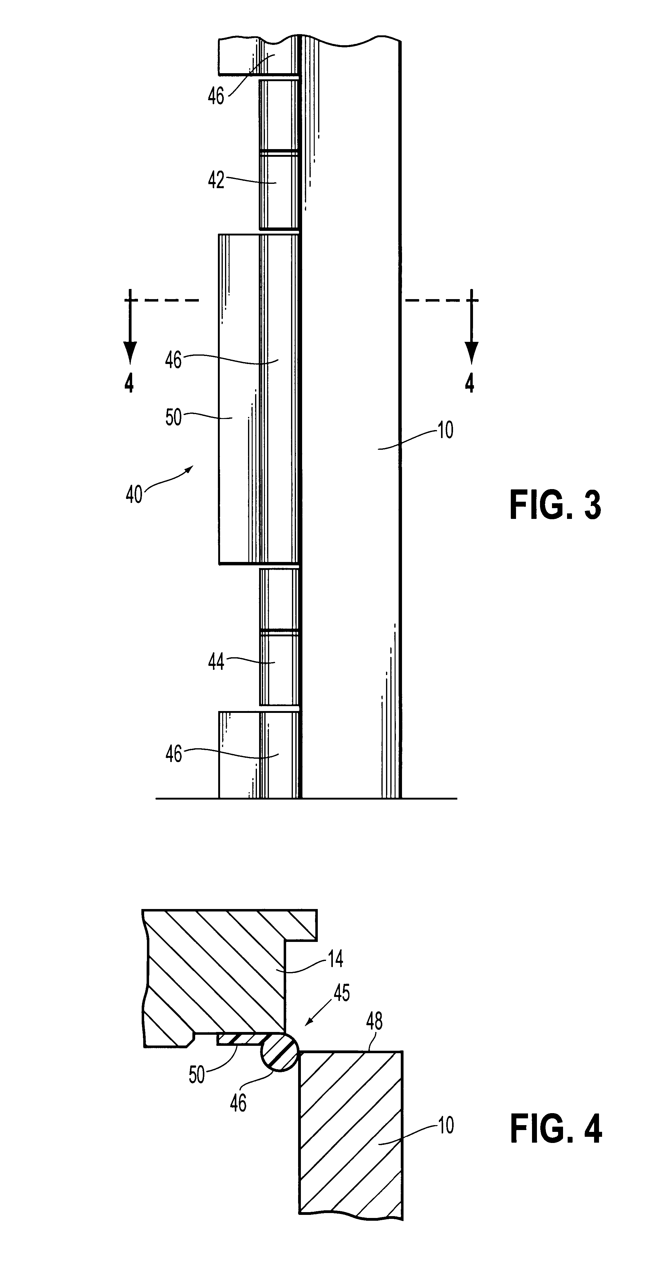
FIGS. 3 and 4 show the protection device 40 for the apparent side of the door. As shown in FIGS. 3 and 4, the protection unit 40 comprise tubular elements 46 in the form of elongated profiled parts on the apparent side of the hinges 42, 44 (FIGS. 1, 3 and 4). These tubular elements 46 are fitted in vertical alignment with the hinges 42, 44 in such a way as to permanently fill the vertical gap 45 that appears between the frame 14 and the rear edge 48 of the door 10 when pivoting of the door takes place. Each tubular element 46 presents a diameter close to that of the hinges 42, 44, and is provided with a flat fixing tab 50 able to be assembled eit...


PUM


Abstract

A safety device for a door is arranged to prevent access to the vertical gap situated on the side where the hinges are located between the frame and the rear edge of the door. The safety device comprises a protection unit having at least one tubular element fitted in the gap in vertical alignment with the hinges, and a strip made of flexible or semi-rigid material arranged on the side opposite the tubular element. The fixing part for fixing the strip onto the frame comprises a rounding unit for rounding the strip over the whole height thereof so as to perform preliminary bending of the strip at a predetermined angle. The strip and the plate extending down to the bottom of the door to achieve total protection.

Description

The invention relates to a mechanical safety device for a door pivotally mounted in a frame between an open position and a closed position, the device being equipped with protection means to prevent fingers from getting jammed when the door is closed, by preventing access to the vertical gap arranged on the side where the hinges are located between the frame and the rear edge of the door by means of a strip made of flexible or semi-rigid material fixed to the frame and cooperating in the intermediate part with a guiding part to arrange a pre-determined clearance with respect lo the door, authorizing a relative sliding movement of the free end of the strip when angular variation of the gap takes place, the guiding pant being fixed to the door by assembly elements.STATE OF THE TECHNIQUERisks of fingers getting jammed between the door and the support frame can occur on the side where the closing handle is situated, and on the side where the hinges are located as a result of deliberate ...

Claims


Application Information

Patent Timeline
Patent Type & Authority Patents(United States)
IPC IPC(8): E06B7/36E06B7/00
CPCE06B7/367
Inventor DELEFOSSE, BRUNOBURDEL, RAYMONDRINGEVAL, CHRISTOPHE
Owner DELEFOSSE BRUNO
Learn More