Very high power radiofrequency generator

Inactive Publication Date: 2001-10-09
THOMSON TUBES ELECTRONIQUES
View PDF10 Cites 3 Cited by
  • Summary
  • Abstract
  • Description
  • Claims
  • Application Information

AI Technical Summary

Problems solved by technology

Nonetheless, they still present certain problems.
In these conditions, the capacitors between the two walls of the coaxial input cavity and respectively the cathode and the grid, of the same type as those in FIG. 1, will be ineffective.
Decoupling becomes difficult to achieve because the r

Method used


Image

  • Very high power radiofrequency generator
  • Very high power radiofrequency generator
  • Very high power radiofrequency generator

Examples


Embodiment Construction

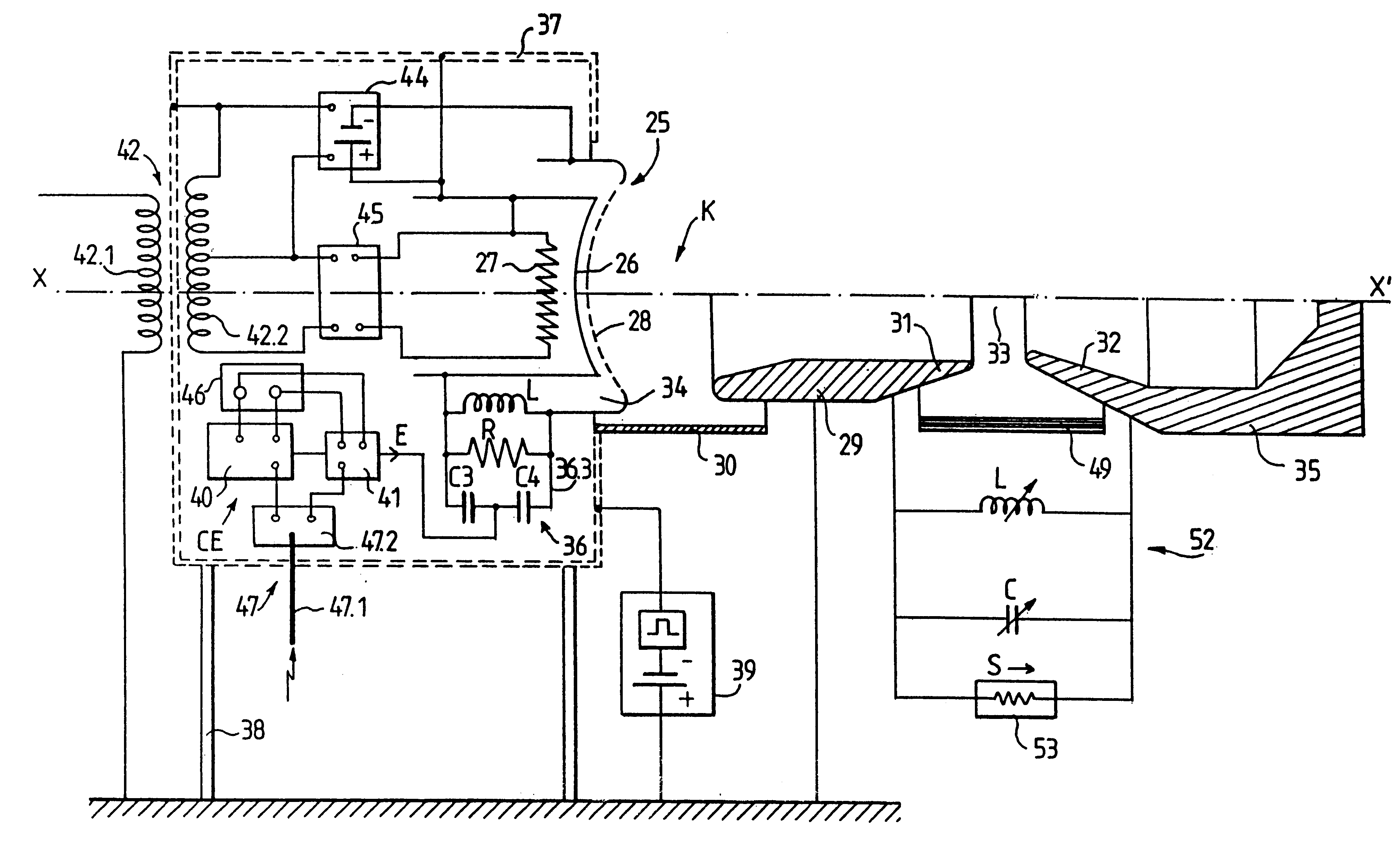
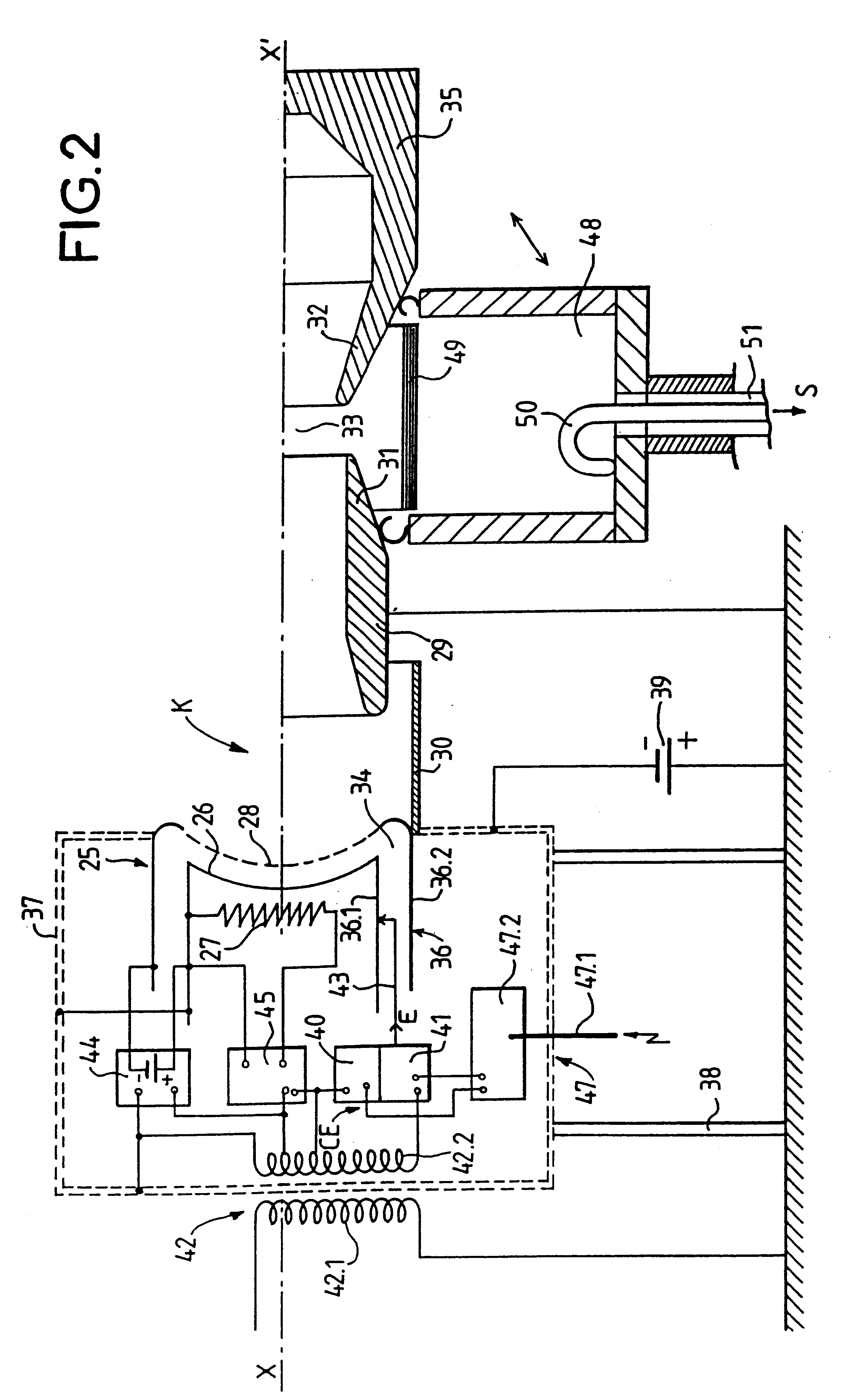
The various characteristics of the generator according to the invention could be obtained with configurations other than those shown in FIGS. 2 and 3. In particular, other combinations of the configurations shown in FIGS. 2 and 3 are possible.

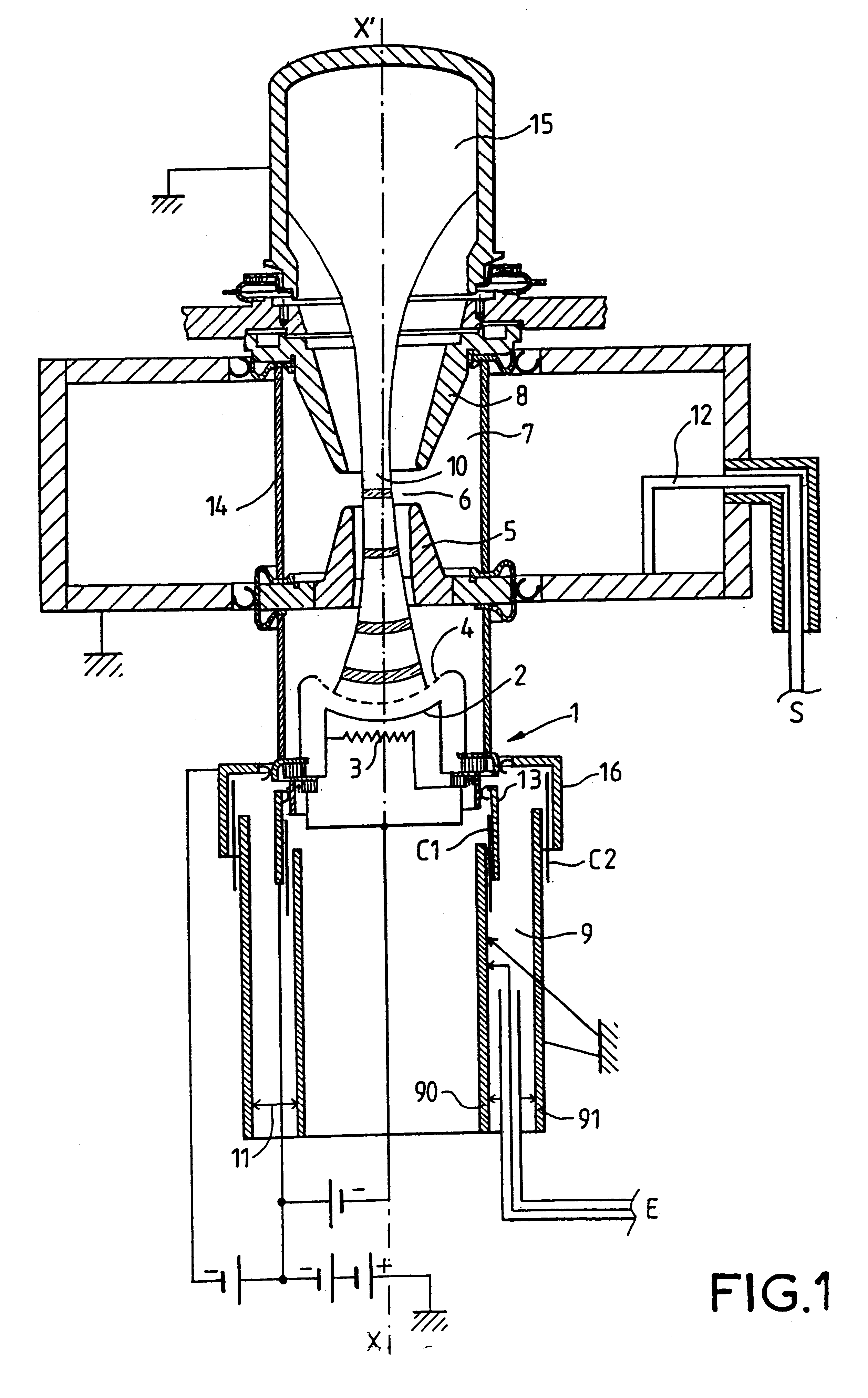
The radiofrequency generator according to the invention illustrated in FIGS. 2 and 3 includes means CE to produce an input radiofrequency signal E to be amplified and means 36 to feed it to an IOT referenced K which supplies an output signal S whose power is amplified compared with the input signal E. The IOT K bears some resemblance to the classical tube described with reference to FIG. 1. The gun 25 is found again with a cathode 26 equipped with a heater 27 and a grid 28 separated from the cathode 26. The function of the gun 25 is to emit an electron beam (not shown for reasons of clarity) via an anode 29 electrically isolated from the gun 25 by a dielectric sleeve 30. The anode 29 in the form of a drift tube ends with a lip 31 which, in comb...


PUM


Abstract

The disclosure relates to a radiofrequency generator including an Inductive Output Tube with an electron gun followed by an anode, the gun being raised to a high voltage in use, means producing an input radiofrequency signal and means of transmitting it to said IOT such that it provides an output signal whose power is amplified compared to said input signal, wherein said means producing said input radiofrequency signal, said means transmitting it to said IOT and said gun are confined in an electrostatically screened enclosure that is electrically isolated from the potential of the anode and can be raised to a high voltage, said gun receiving its high voltage from said screened enclosure. The invention is applicable to very high power radiofrequency generators.

Description

The invention relates to radiofrequency generators of very high power. These generators, used notably for scientific applications, must operate at frequencies of the order of 20 to 200 MHz, or even slightly higher, and in a pulsed regime provides peak powers of several tens of megawatts. In the continuous regime the powers are significantly lower.DESCRIPTION OF THE PRIOR ARTThese generators make use of vacuum tubes. At these frequencies classical grid tubes such as tetrode-type tubes are limited to a few megawatts of power, the present limit being about 10 MW.Klystrons can supply these powers but they work at microwave frequencies, in other words much higher frequency.Inductive Output Tubes (IOT) are used in the frequency range of the grid tubes at much smaller powers; they are mainly used in UHF television transmitters. They are configured as shown in FIG. 1. By adapting their input and output resonant circuits to the desired frequency they can also be used at shortwave and VHF fre...

Claims


Application Information

Patent Timeline
IPC IPC(8): H01J23/14H01J25/00H01J25/04H01J23/34H01J23/38H01J23/00
CPCH01J23/14H01J23/34H01J23/38H01J25/04
Inventor CLERC, GUY
Owner THOMSON TUBES ELECTRONIQUES
Why Eureka
Try Eureka