Control system using an electric motor
a control system and electric motor technology, applied in the direction of circuit-breaking switches, circuit-breaking switches for excess current, emergency protective arrangements responsive to undesired changes, etc., can solve the problem of inability to determine the exact overload signal
- Summary
- Abstract
- Description
- Claims
- Application Information
AI Technical Summary
Problems solved by technology
Method used
Image


Examples
Embodiment Construction
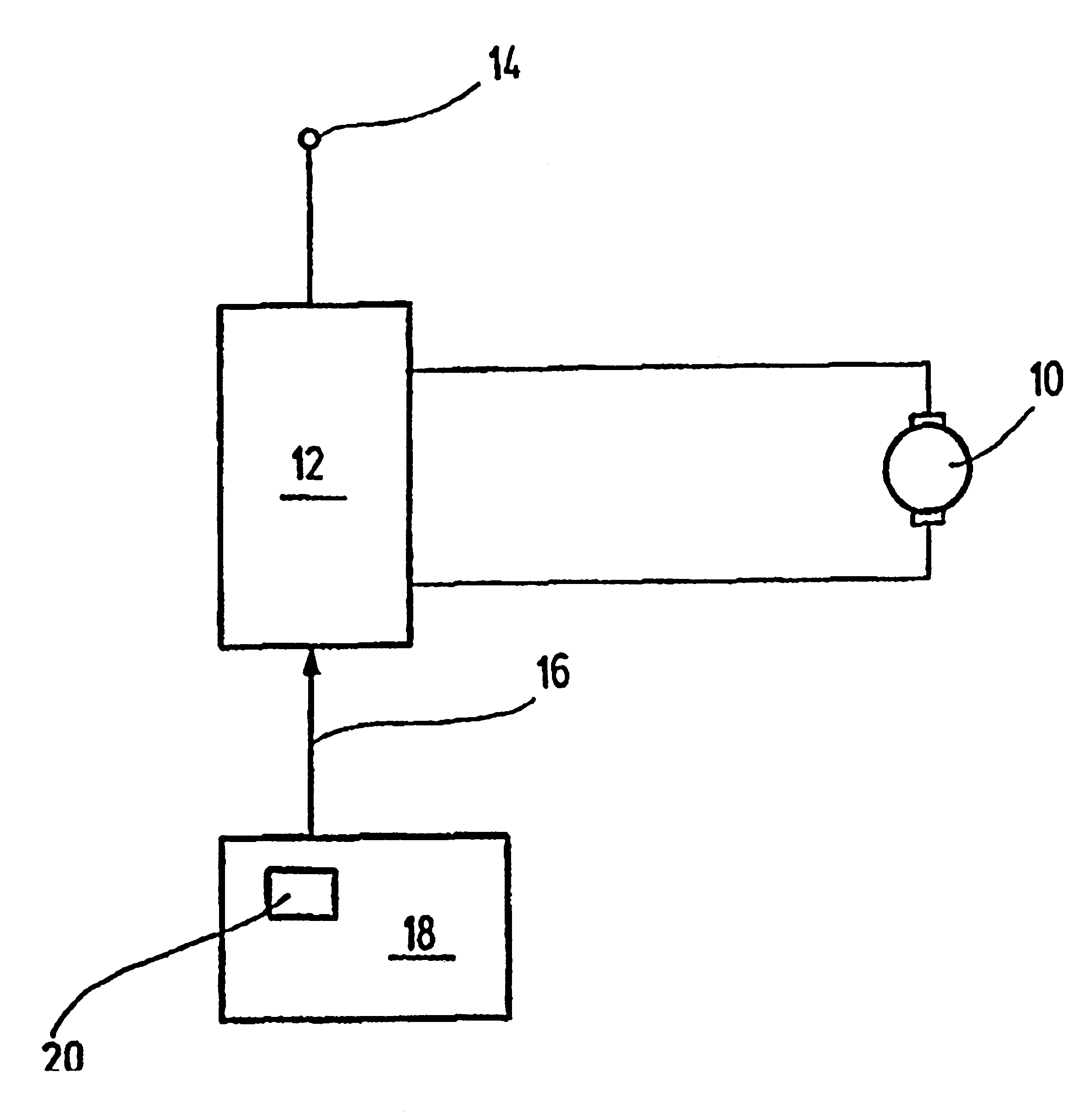
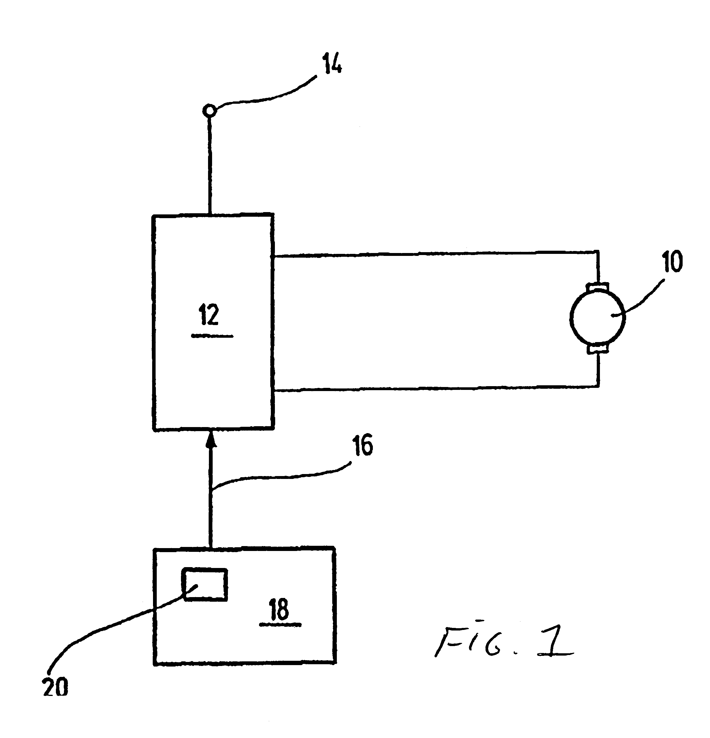
FIG. 1, in a block circuit diagram, shows an electric motor drive. The electric motor drive includes a direct current motor 10, which acts for instance as a control motor in a motor vehicle. The direct current motor 10 is connected to an end stage 12, which has switch means for connecting the direct current motor 10 to an energy source 14. In motor vehicles, the energy source is a motor vehicle battery, for example. The switching stage 12 is supplied with a control signal 16, which is furnished by a trigger circuit 18. By means of the trigger circuit 18, a pulse-width-modulated triggering of the switching stage 12 is effected, so that a clocked mode of operation of the direct current motor 10 is
During the intended use of the direct current motor 10, this motor, for instance from sluggishness or the presence of an obstacle in a controlled path of a final control element that is movable with the direct current motor 10, can become mechanically and thermally overloaded, so that tempera...
PUM
 Abstract
Description
Claims
Application Information