Shielded cable and connector assembly

a shielding cable and connector technology, applied in the direction of electrically conductive connections, coupling device connections, electrical apparatus, etc., can solve the problems of cracking of plastic, insufficient shielding effect of shielding effected in this manner, and insufficient shielding effect of commercially available cable and connector assemblages,

Inactive Publication Date: 2001-10-16
INTERCONNECT
View PDF5 Cites 38 Cited by
  • Summary
  • Abstract
  • Description
  • Claims
  • Application Information

AI Technical Summary

Problems solved by technology

The shielding effect provided by commercially available cable and connector assemblages, such as STP-cable and connector assemblages (Shielded Twisted Pair) and FTP-cable and connector assemblages (Foil-shielded Twisted Pair) has been found insufficient in the case of sensitive applications.
Shielding effected in this manner has also been found insufficient.
Conventional clamping or squeezing of the conductors causes the conductors to be pressed together under pressure, resulting in deformation.
This often results in cracking of the plastic ?

Method used


Image

  • Shielded cable and connector assembly
  • Shielded cable and connector assembly
  • Shielded cable and connector assembly

Examples


first embodiment

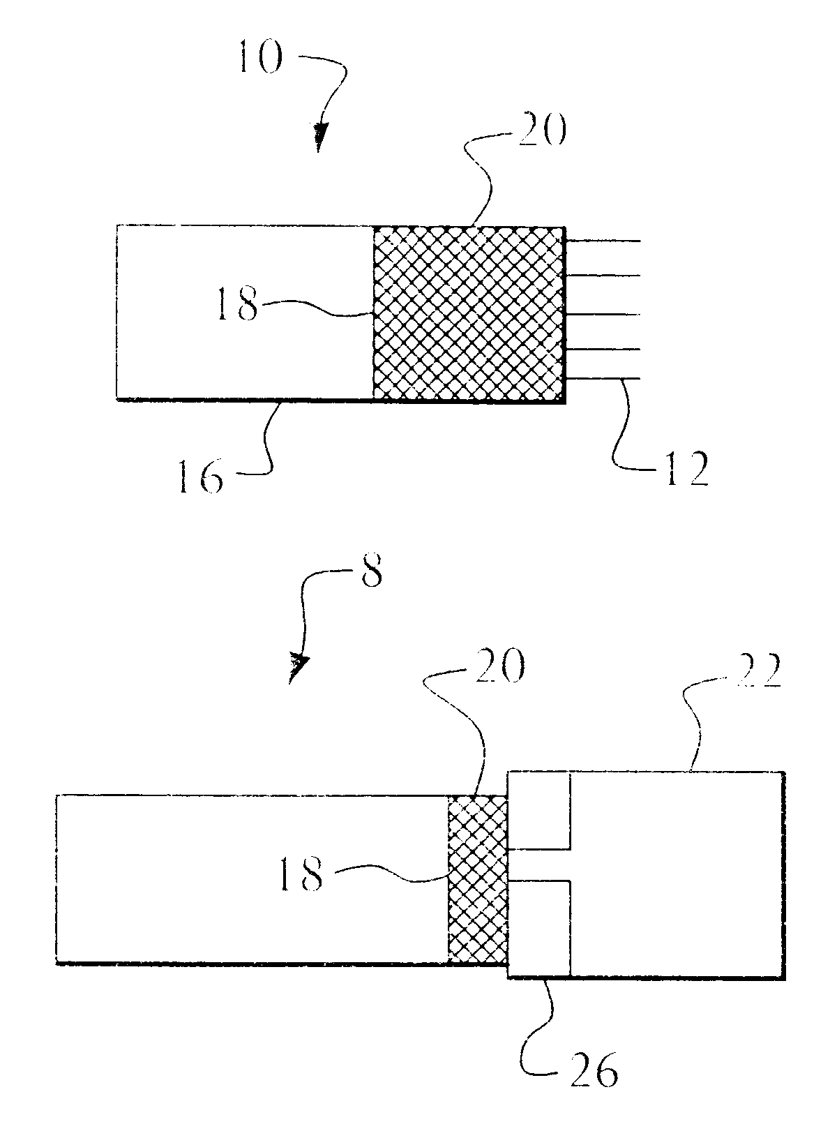
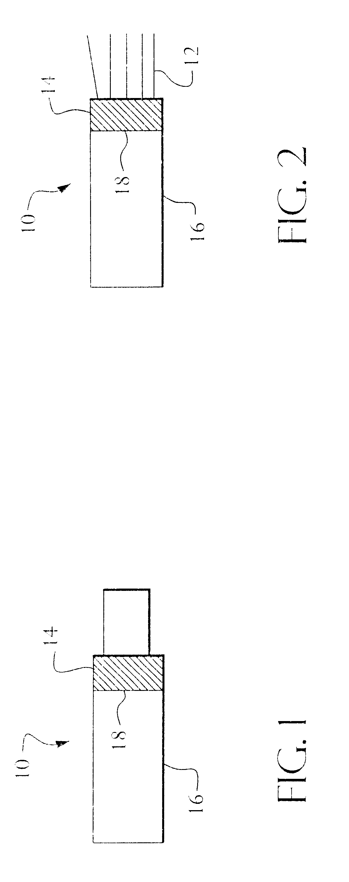
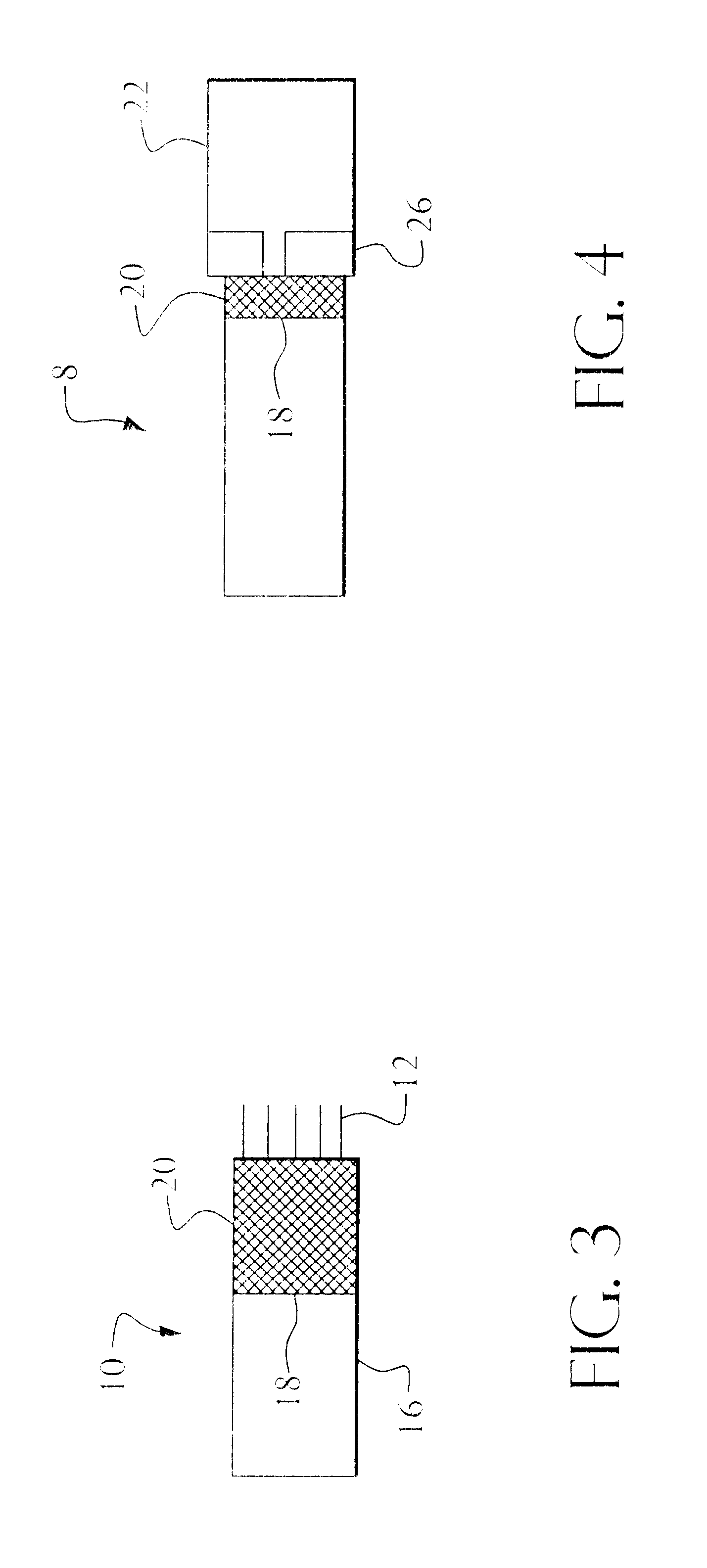
FIG. 1 is a side view showing a cable 10 in one stage of the fabrication of a shielded cable-connector assemblage according to the invention. The illustrated cable 10 has an outer cable mantle 16. Part of the components of the cable 10 have been peeled off or removed with the aid of an appropriate tool and a part 14 of the braided metal shield has been folded back over the outer mantle 16 of the cable. Part of the folded-back braided metal shield 14 has also been twisted to form a connection lead 18. FIG. 2 shows the cable 10 after the conductors 12 have been bared (the cable is shown to include five conductors 12). FIG. 3 is a side view of the cable and shows the cable subsequent to having fitted a shielding element 20 thereto. As evident from FIG. 3, the shielding element embraces the cable mantle 16 and the conductors 12 and covers fully the junction between the backwardly folded braided metal shield and the conductors 12. As will also be evident from FIG. 3, The length of the sh...

second embodiment

A second embodiment of a method of fabricating a shielded cable-connector assemblage and a shielded cable-connector assemblage fabricated in accordance with the method will now be described also with reference to FIGS. 1-5 of the accompanying drawings, even though said second embodiment differs from the first embodiment in some respects. The main differences between the first and the second embodiments is that the braided metal shield is not twisted to form a connection lead 18 and that no shielding element 20 in the form of copper foil is provided. The twisted lead 18 and the shielding element 20 can thus be deleted from the drawings with respect to an illustration of the present invention. In a first stage of fabricating a cable-connector assemblage 8 according to the second embodiment, part of the cable components are peeled off or removed and part of the braided metal shield is then folded back over the cable mantle. The conductors 12 are then bared and each cable 10 is fitted w...


PUM


Abstract

The present invention relates to a method of fabricating a shielded cable-connector assemblage (8) and to a shielded cable-connector assemblage (8) fabricated in accordance with the method. The assemblage (8) comprises at least one cable (10) which includes, among other things, conductors (12), a braided metal shield (14), and an outer mantle (16), and further comprises a connector (22). The method comprises the steps of folding a part of the braided metal shield (14) back over the outer mantle surface (16) of the cable; mounting a shielding element (20) so as to cover the whole of the junction between the backwardly folded braided metal shield (14) and the conductors (12) and to be in electrical contact with the braided metal shield (14); fitting a connector (22) to each cable (10) to form a cable-connector assembly; fixedly mounting each cable-connector assembly (10, 22) in a molding device; and molding a strain relieving element (28) such as to fill the space between the cable (10) and the connector (22) and to fixate said cable and connector in relation to one another.

Description

The present invention relates to a method of fabricating shielded cable assemblages, and to a cable and connector assemblage fabricated in accordance with the method. By cable and connector assemblage is meant an assemblage which includes one or more cable-connector assemblies.RELATED PRIOR ARTThe shielding effect provided by commercially available cable and connector assemblages, such as STP-cable and connector assemblages (Shielded Twisted Pair) and FTP-cable and connector assemblages (Foil-shielded Twisted Pair) has been found insufficient in the case of sensitive applications. Present day cable shielding is achieved, for instance, by folding back part of the braided metal shield and soldering it to a metal surface on the connector. Shielding effected in this manner has also been found insufficient.The present inventions aims to solve these problems. This aim is achieved with a method of fabricating shielded cable and connector assemblages in accordance with claim 1 or claim 5, a...

Claims


Application Information

Patent Timeline
Patent Type & Authority Patents(United States)
IPC IPC(8): H01R9/05H01R13/58H01R43/00H01R13/658H01R9/03
CPCH01R9/034H01R9/035H01R9/05H01R13/5845H01R43/00H01R24/62H01R13/6592H01R13/65914H01R13/65915
Inventor HOLMSTROM, BJORN
Owner INTERCONNECT
Why Eureka
Try Eureka