Mounting device for mounting a data storage device

a data storage device and mounting device technology, applied in the direction of casings/cabinets/drawers, instruments, casings/cabinets/drawers details of electrical apparatus, etc., can solve the problems of affecting the electrostatic discharge process, affecting the mounting position of data storage devices, and poor engagement between data storage devices and computer enclosures

Inactive Publication Date: 2001-10-16
HON HAI PRECISION IND CO LTD
View PDF13 Cites 55 Cited by
  • Summary
  • Abstract
  • Description
  • Claims
  • Application Information

AI Technical Summary

Benefits of technology

The fingers 36, 40 of the grounding clip 14 respectively contact the computer enclosure 70 and the CD-ROM 50 after the CD-ROM 50 is mounted in the computer enclosure 70 thereby forming a grounding path between the computer enclosure 70 and the CD-ROM 50 for electrostatic discharge purposes. Furthermore, the fingers 36, 40 provide the grounding clip 14 with compliant properties thereby facilitating smooth engagement between the CD-ROM 50 and the mounting bracket 72 of the computer enclosure 70.

Problems solved by technology

This process is tedious and laborious.
However, rails made of insulative material, such as plastic, hinder the electrostatic discharge process.
Such a spring member has fatigue problems leading to poor engagement between the data storage device and the computer enclosure.

Method used


Image

  • Mounting device for mounting a data storage device
  • Mounting device for mounting a data storage device
  • Mounting device for mounting a data storage device

Examples


first embodiment

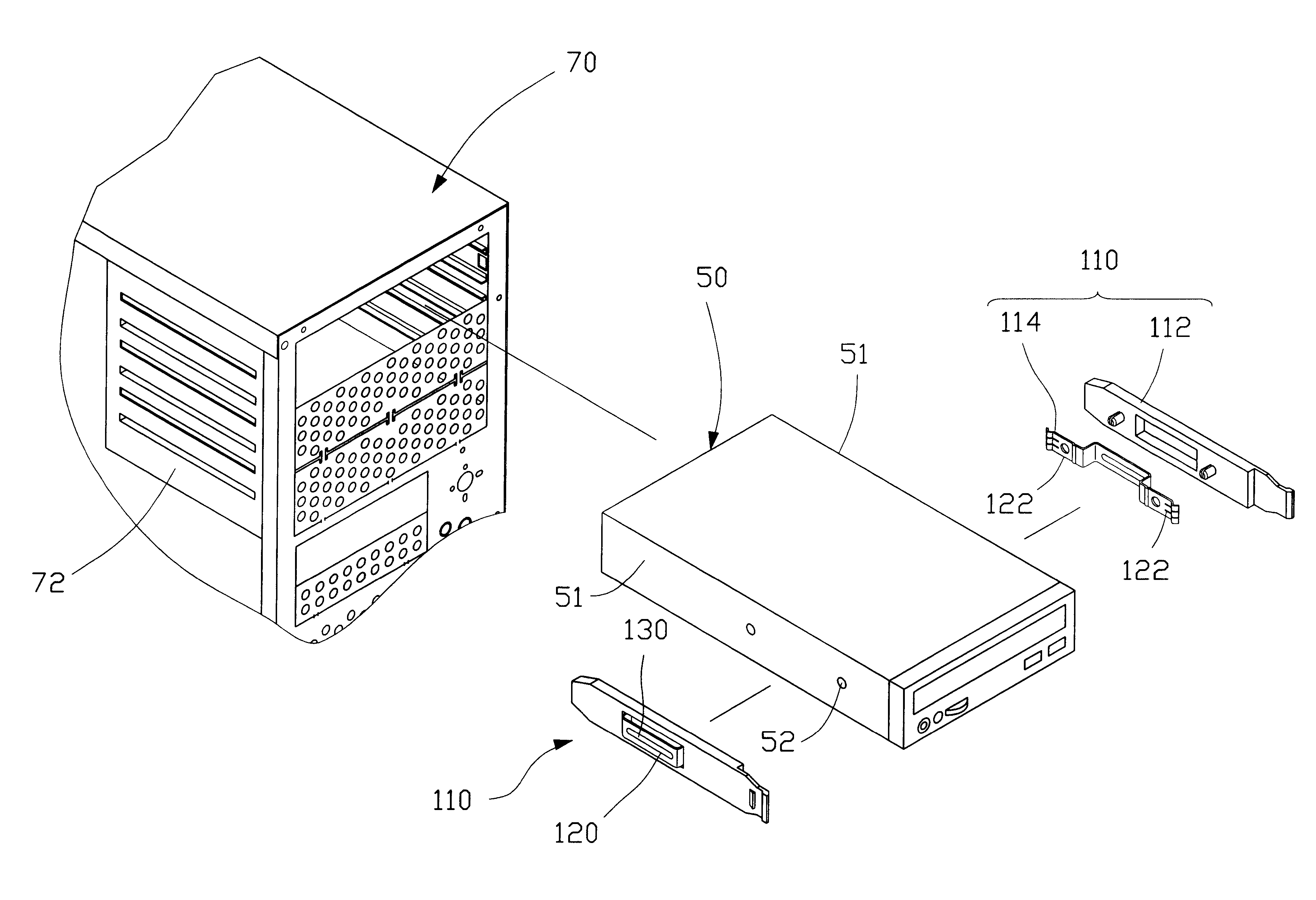
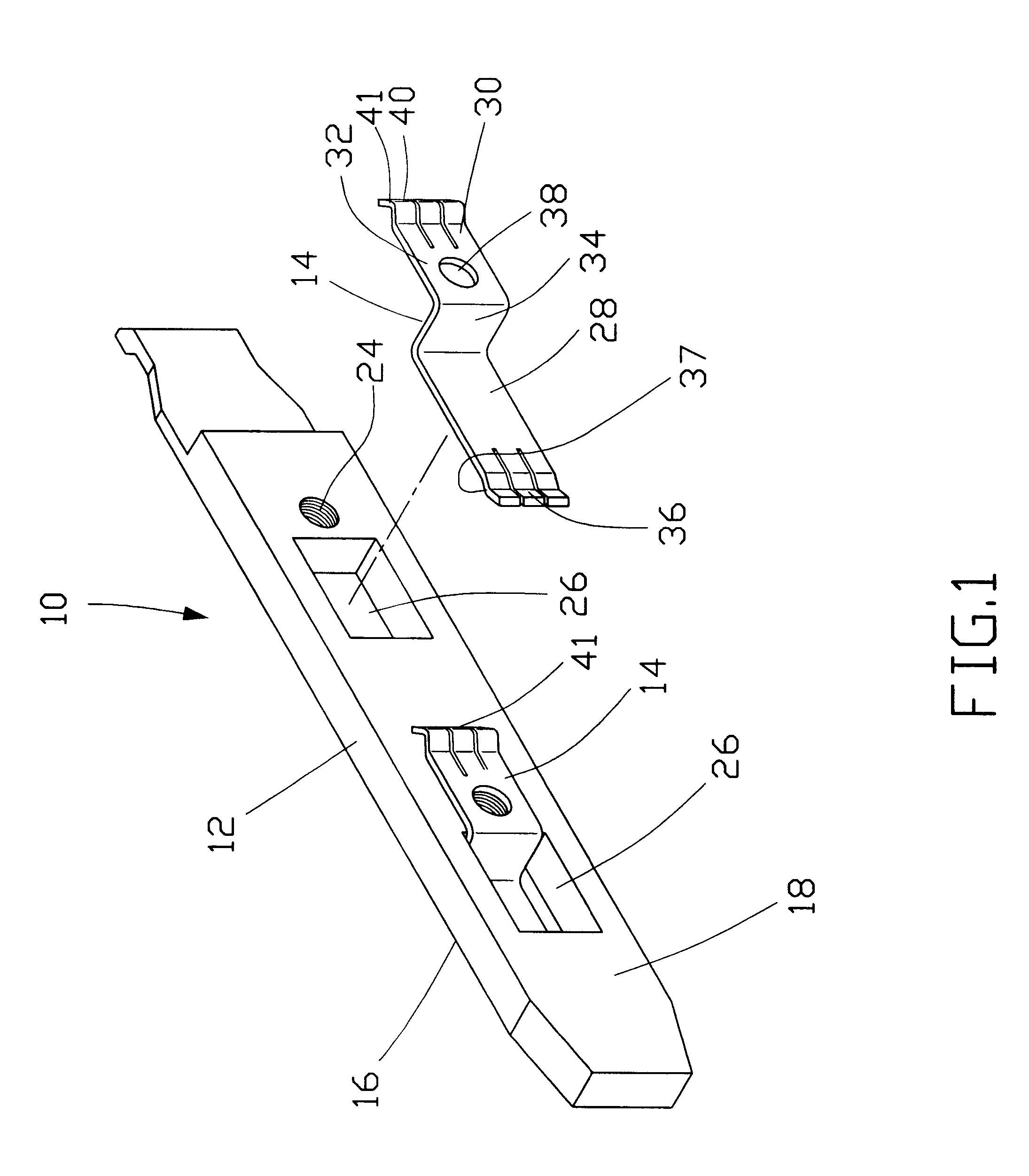
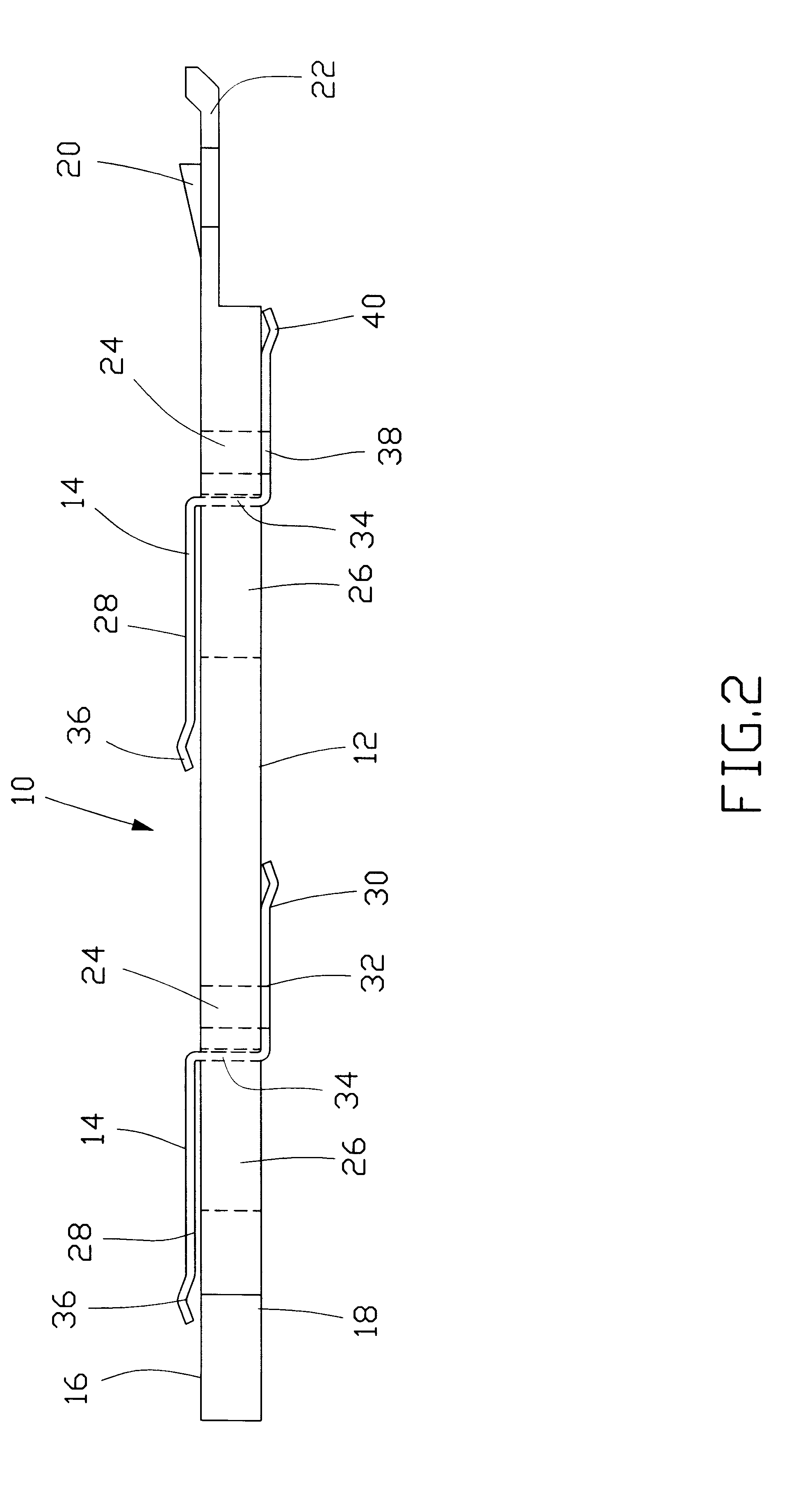
Referring to FIGS. 1-3, a pair of mounting devices 10 in accordance with the present invention mount a CD-ROM 50 to a computer enclosure 70. Each mounting device 10 comprises a board body 12 and grounding clips 14. The board body 12 is a rectangular plastic board abutting against one side of the CD-ROM 50. The board body 12 has a first surface 16, an opposite second surface 18 abutting against one side 51 of the CD-ROM 50, a barb 20, a pulling portion 22, two through holes 24 and two elongate slots 26.

Each grounding clip 14 comprises a first section 28, a second section 30 and a securing section 32. The first section 28 and the securing section 32 are connected by a step 34. The first section 28 and the second section 30 each form a plurality of first and second fingers 36, 40. The first and second fingers 36, 40 form convex arcs 37, 41 at free ends thereof. The securing section 32 forms a hole 38. The step 34 is received in the slot 26 with the first section 28 abutting against the...

second embodiment

FIGS. 4 and 5 illustrate the mounting device 110 of the present invention. The mounting device 110 comprises a board body 112 and a grounding clip 114. The board body 112 defines an elongate slot 116 and forms two securing posts 118 on opposite sides of the slot 116. The grounding clip 114 comprises a first section 120 and a pair of second sections 122 and securing sections 124 formed on opposite ends of the grounding clip 114. The first section 120 and the securing sections 124 are connected by steps 126. Each second section 122 forms fingers 123 each having an end convex free end 125. Each securing section 124 forms a hole 128 for extension of the corresponding securing post 118 therethrough. Each securing post 118 forms a slit 119 for facilitating engagement between the securing posts 118 and the screw holes 52 of the CD-ROM 50. Thus, the two of the mounting devices 110 are mounted to the opposite sides of the CD-ROM 50. The CD-ROM 50 is received in the mounting bracket 72 of the...


PUM

PropertyMeasurementUnit
electrically insulativeaaaaaaaaaa
conductiveaaaaaaaaaa
flexibilityaaaaaaaaaa

Abstract

A mounting device for mounting a data storage device to a receiving bracket of a computer enclosure includes a board body and at least one grounding clip. Two of the mounting devices are attached to opposite sides of the data storage device and engage with the receiving bracket. Each grounding clip includes a securing section, a first section and a second section. A bolt extends through a hole defined in the securing section of the grounding clip and a through hole defined in the board body for engaging with a screw hole defined in the data storage device thereby fixing the grounding clip and the board body to the data storage device. The fist and second sections of each grounding clip form a plurality of fingers for respectively contacting the data storage device and the computer enclosure thereby forming a grounding path therebetween while fixing the data storage device to the computer enclosure.

Description

1. Field of the InventionThe present invention relates to a mounting device for mounting a data storage device to a computer enclosure, and particularly to a mounting device having grounding fingers for providing a grounding function and fixing the data storage device to a computer.2. The Related ArtData storage devices normally used in a personal computer include a hard disk drive (HDD), a floppy disk drive (FDD) and a compact disc read only memory (CD-ROM). A data storage device is often fixed in a receiving bracket of a computer by bolts. When mounting the data storage device to the computer enclosure, an assembler must align the CD-ROM with the receiving bracket with one hand and tighten the bolts with the other hand. This process is tedious and laborious. Therefore, rails are attached to both sides of a CD-ROM to simplify the installation process.Rails made from conductive material, such as metal, promote electrostatic discharge of the data storage device. However, rails made o...

Claims


Application Information

Patent Timeline
Patent Type & Authority Patents(United States)
IPC IPC(8): G06F1/18G11B33/12H05K9/00
CPCG06F1/184G06F1/187H05K9/0016H05K9/0067G11B33/124Y10T24/44923
Inventor LIU, ALVINFU, SHAO-MING
Owner HON HAI PRECISION IND CO LTD
Why Eureka
Try Eureka