
Aircraft cabin seat configuration with enhanced ingress/egress

Inactive Publication Date: 2001-10-23
B E AEROSPCAE
View PDF21 Cites 117 Cited by
  • Summary
  • Abstract
  • Description
  • Claims
  • Application Information

AI Technical Summary

Benefits of technology

It is another object of the invention to provide a seat configuration for an aircraft cabin which provides enhanced ingress and egress for a seat occupant seated adjacent an aircraft window side of the aircraft outboard of a seat adjacent an aisle in the aircraft cabin.
It is another object of the invention to provide a seat configuration for an aircraft cabin wherein the occupant of a window seat can ingress to and egress from the scat without disturbing the occupant in the adjacent aisle scat while the aisle seat is in any seating position.
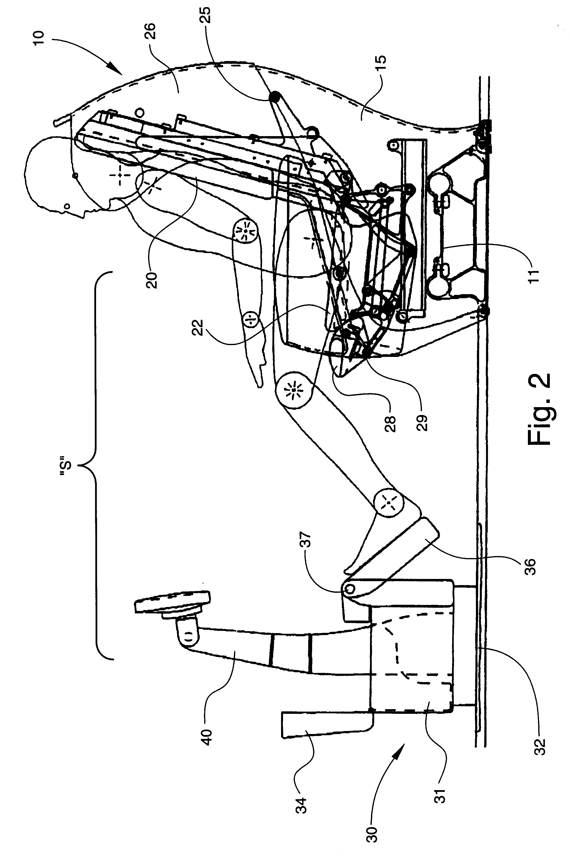
This position is also shown in FIG. 3, where is also illustrated the staggered configuration of adjacent seating units "S". This position provides greater privacy for adjacent seat occupants and also permits the "window" seat occupant to leave and return to the seat between the two ottomen 34 without disturbing the "aisle" seat occupant.

Problems solved by technology

One particular problem encountered in prior art sleeper seats is that the length and configuration of the inboard aisle seat, when in the reclined sleeping position traps the occupant of the outboard window seat in the seat by blocking access to the aisle.
This is a significant problem, particularly on long-haul flights during which passengers may wish to sleep for several hours without being disturbed.
However, this is an impractical solution given the necessity of fitting a given amount of passenger load within a given space.
In addition, too great a distance between adjacent seats prevents conversation and social interaction between passengers traveling together.

Method used


Image

  • Aircraft cabin seat configuration with enhanced ingress/egress
  • Aircraft cabin seat configuration with enhanced ingress/egress
  • Aircraft cabin seat configuration with enhanced ingress/egress

Examples


Embodiment Construction

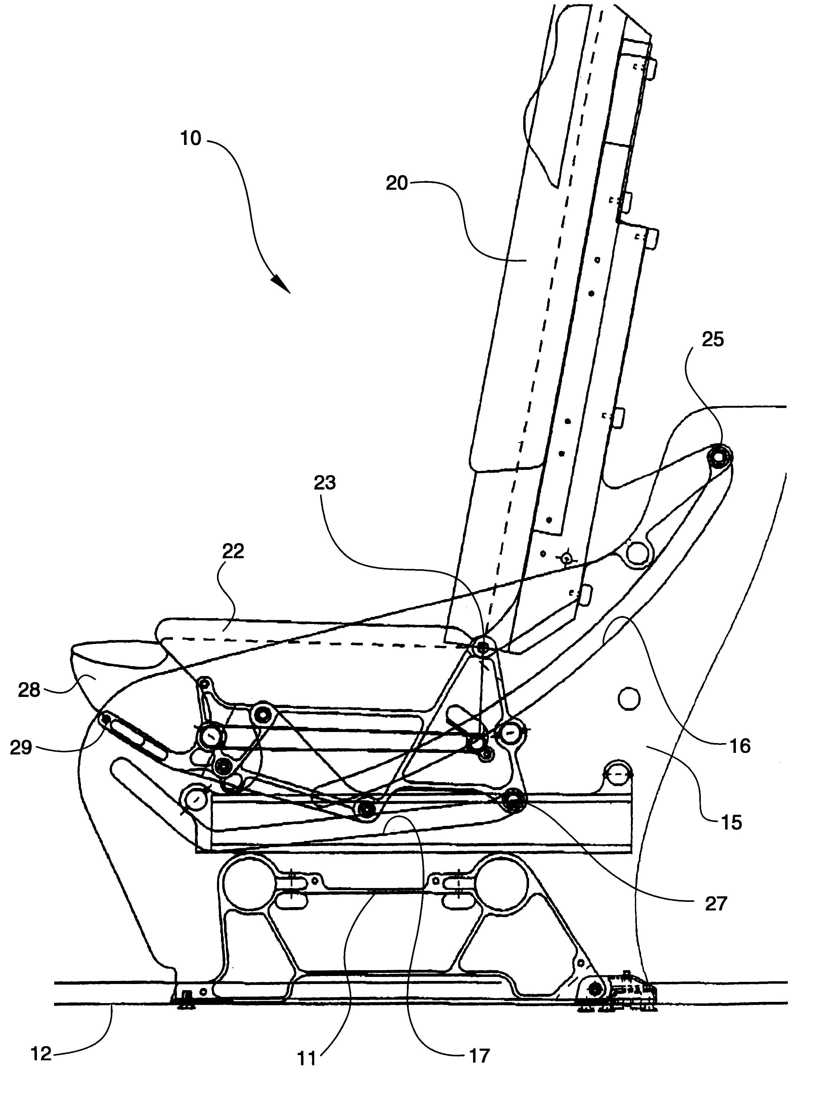
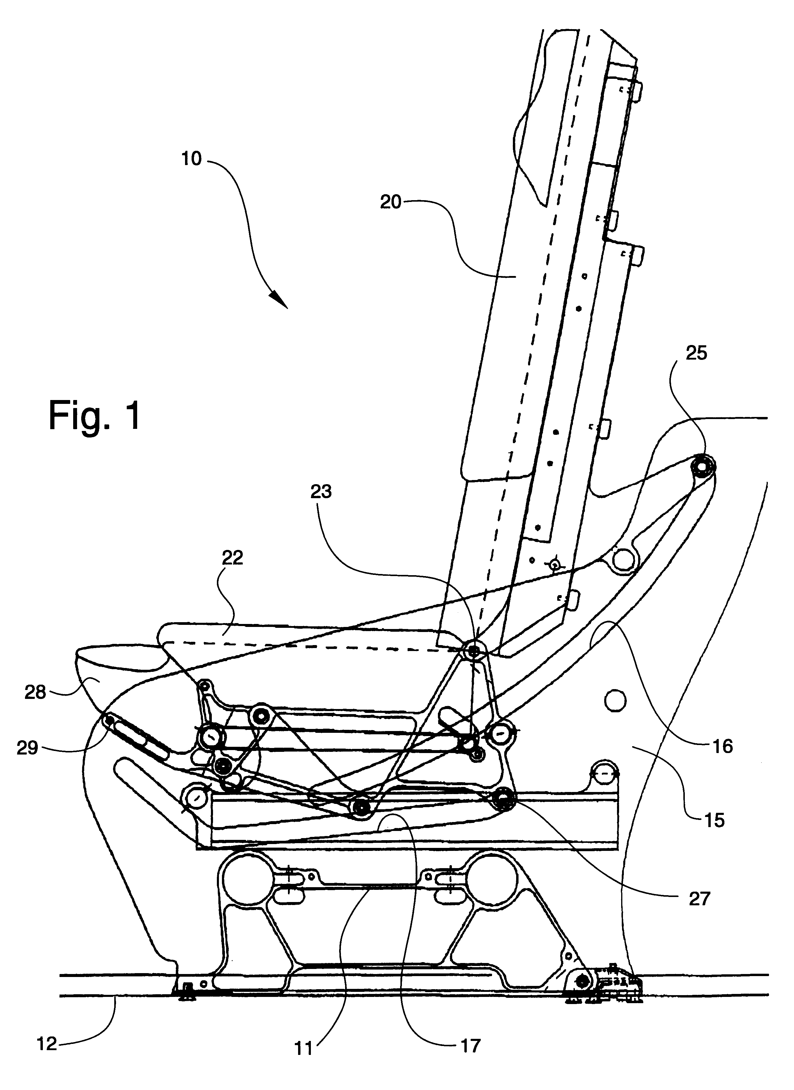
Referring now specifically to the drawings, a first class sleeper seat according to the present invention is illustrated in FIG. 1 and shown generally at reference numeral 10. Seat 10 includes a seat frame 11 which is attached to a track 12 mounted on the deck of an airplane. Attachment is made by use of track fittings, such as those disclosed in applicant's U.S. Pat. No. 5,871,318. The seat frame 11 includes a pair of horizontally spaced-apart side supports 15 in which are formed a pair of elongate guide slots 16, 17. Slots 16, 17 guide movement of a seat back 20 and seat bottom 22, respectively. Seat back 20 and seat bottom 22 are joined for pivotal movement relative to each other by pivot pin 23.

Scat back 20 is mounted between side supports 15 by guide pins 25 mounted for sliding movement in guide slots 16. Likewise, seat bottom 22 is mounted between side supports 15 by guide pins 27. Seat movement occurs by operation of electric motors (not shown) in a conventional manner. The s...


PUM


Abstract

A passenger seat configuration for an aircraft cabin having a fuselage wall with windows therein and an aisle for permitting movement within the cabin. The configuration includes an outboard seating unit for being positioned adjacent the fuselage wall of the aircraft, the outboard seating unit having a primary scat formed of a seat back and seat bottom, and a forwardly spaced-apart ottoman movable with respect to each other to define upright, semi-reclined and fully reclined positions. An inboard seating unit is provided for being positioned adjacent the at least one aisle and between the inboard seating unit and the aisle, the inboard seating unit having a primary seat formed of a seat back and a seat bottom, and a forwardly spaced-apart, free-standing ottoman movable with respect to each other to define upright, semi-reclined and fully reclined positions, the primary seat and ottoman of the inboard seating unit being positioned aft of the primary seat and ottoman of the outboard seating unit. The ottoman of the outboard seating unit and the ottoman of the inboard seating unit are independently movable relative to each other whereby the outboard ottoman is movable to a position relative to any position of the inboard ottoman to thereby provide space between the inboard ottoman and outboard ottoman for the outboard passenger to ingress to and egress from the outboard primary seat between the inboard ottoman and outboard ottoman and forward of the inboard ottoman to the aisle.

Description

TECHNICAL FIELD AND BACKGROUND OF THE INVENTIONThis invention relates to an aircraft cabin seat configuration with enhanced ingress and egress for the occupant of the seat adjacent the window of the aircraft. The application also discloses a sleeper seat which permits enhanced ingress and egress for the window-side passengers. The size and spacing of the seats renders the configuration most suitable for first class areas of the aircraft. The configuration is particularly suitable for the first class cabins of large, long-haul aircraft such as Boeing 747's. However, similar configurations are also useable in other long-haul aircraft such as Boeing 767's and 777's.The cabin configuration disclosed in this application utilizes a "sleeper" seat. Such types of seats are known, and typically involve a structure which combines a seat back with a seat bottom which has telescoping segments which extend outwardly as the seat back reclines. These extending segments also generally function as l...

Claims


Application Information

Patent Timeline
IPC IPC(8): B60N2/44B64D11/06B64D11/00B60N2/90
CPCB60N2/4495B64D11/00B64D11/0015B64D11/06B64D11/0604B64D11/0601B64D11/0641B64D11/06395B64D11/064B60N2/995B64D11/00153B64D11/0643
Inventor BEROTH, MICHAEL T.
Owner B E AEROSPCAE
Learn More