
Methods and apparatus for adaptive filters

a filter and filter technology, applied in the field of digital processing, can solve the problems of disadvantageous slow processing speed, inconvenient high-speed/precision use architecture, and low processing efficiency, and achieve the effects of saving physical space, saving time during manufacturing, and improving economic benefits

Inactive Publication Date: 2001-10-23
HEWLETT PACKARD DEV CO LP
View PDF4 Cites 4 Cited by
  • Summary
  • Abstract
  • Description
  • Claims
  • Application Information

AI Technical Summary

Benefits of technology

It is another object of the present invention to provide an improved adaptive filter architecture suitable for achieving one or all of the following: low pin counts, fast processing times or reduced numbers of filter elements.
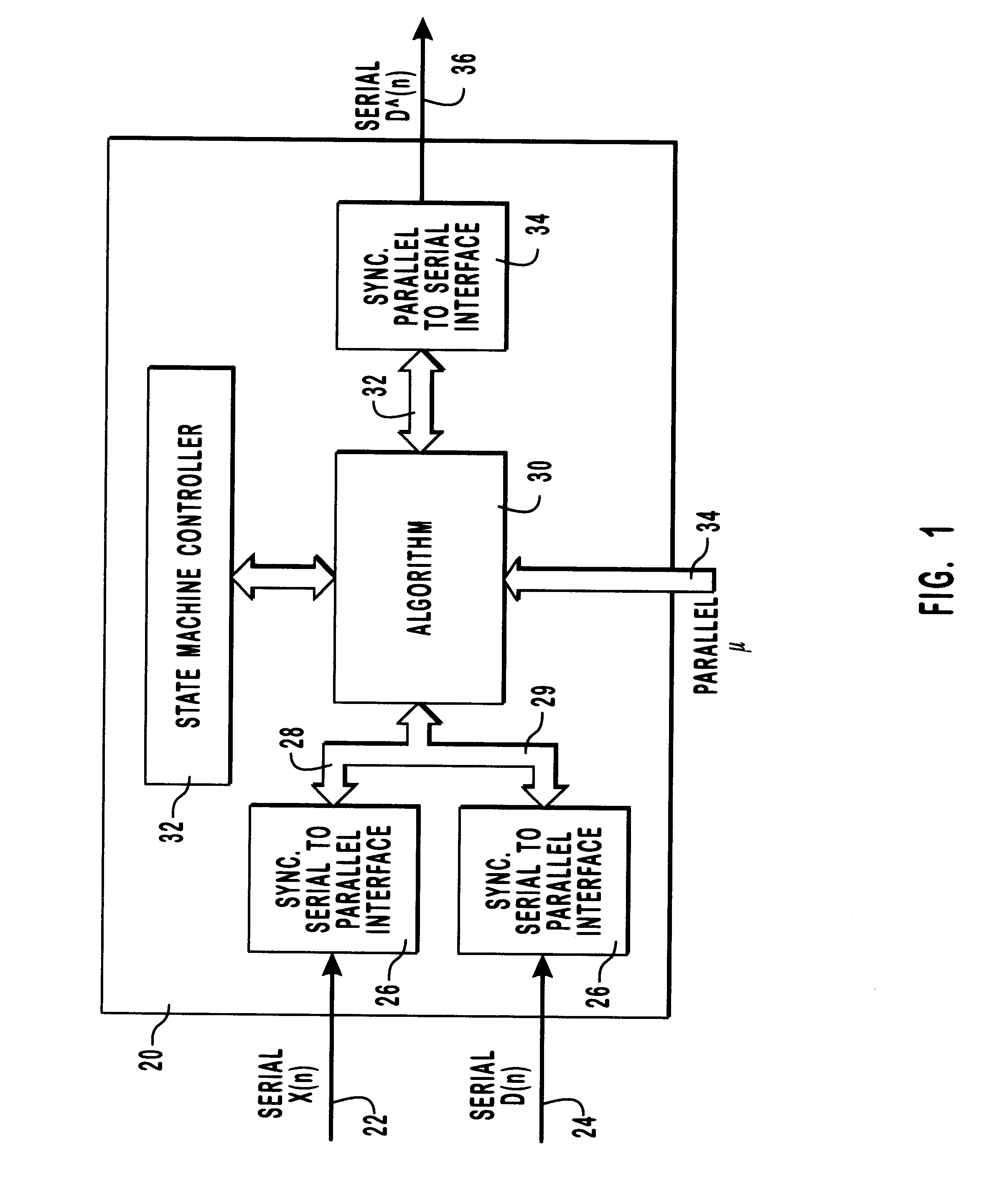
It is also possible to perform adaptive filtering as described herein without first requiring the input signal to be supplied to the adaptive filter as a serial input and then converted into a parallel input. It is possible to merely supply the input signal as a parallel input. In a similar manner, the parallel output signal may also be supplied from the adaptive filter architecture in a parallel manner without undergoing conversion to a serial output signal. These alternatives allow even further advantage because physical space is saved within the adaptive filter and the signal processing does not require multiple parallel to serial, and vice versa, conversions. They, however, adversely increase pin counts.

Problems solved by technology

As for engineering considerations, such as pin count and speed of processing the digital signal, the pin count is advantageously low while the speed of processing is disadvantageously slow.
Thus, this architecture is not suitable for many high-speed / precision uses.
Thus, the speed of processing is fast but the pin count is high.
During manufacturing, this leads to high economic costs in time and labor.
Also, since these elements require large amounts of physical space, silicon costs are high.

Method used


Image

  • Methods and apparatus for adaptive filters
  • Methods and apparatus for adaptive filters
  • Methods and apparatus for adaptive filters

Examples


Embodiment Construction

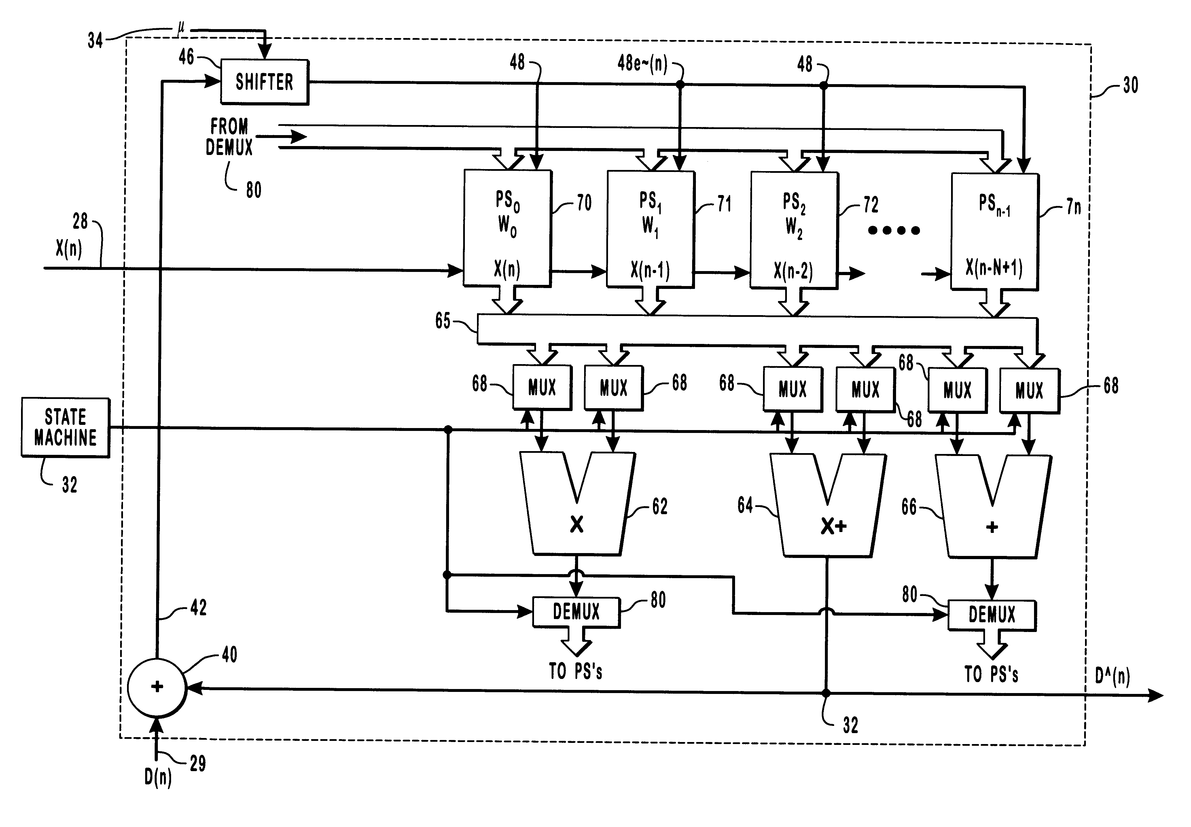
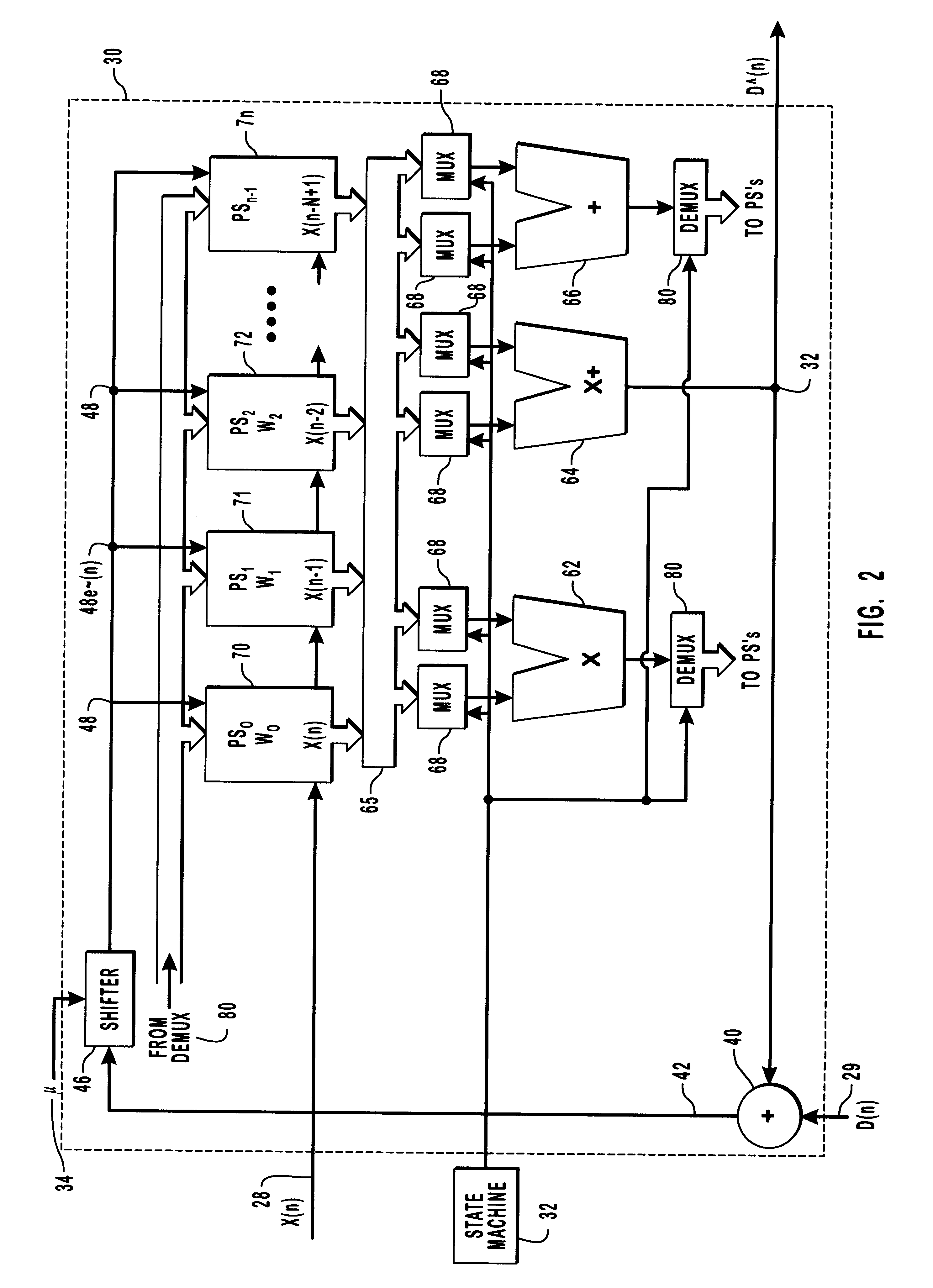
The following serves to illustrate one cycle of the iterative process performed by the foregoing architecture. The coefficients, W, of the adaptive filter 30 are updated within their respective state using present and previous inputs such that the ith processing state performs the following set of calculations:

W.sub.i (n+1)=W.sub.i (n)+X.about.(n); 1)

X.about..sub.i+1 (n)=X.sub.i+1 (n).times.e.about.(n-1); 2)

and

D .sub.i (n)=D .sub.i-1 (n)+W.sub.i (n).times.X.sub.i (n); 3)

where,

W(n)=W(n-1)+[.mu..times.e(n-1).times.X(n)];

D (n)=W(n)*X(n);

e(n)=D(n)-D (n);

and

e.about.(n)=.mu..times.X(n).

Then, at time n:

X.about..sub.0 (n)=X.sub.0 (n).times.e.about.(n); D (n)=0.

The processing states are as follows:

Processing State 0

W.sub.0 (n+1)=W.sub.0 (n)+X.about..sub.0 (n);

X.about..sub.1 (n)=(n).times.e.about.(n);

Processing State 1

W.sub.1 (n+1)=W.sub.1 (n)+X.about..sub.1 (n);

X.about..sub.2 (n)=X.sub.2 (n).times.e.about.(n);

D (n)=D (n)+[W.sub.0 (n+1).times.X.sub.0 (n)];

Processing State 2

W.sub.2 (n+1)=W.sub...


PUM


Abstract

The present invention relates to improved adaptive filtering techniques and architectures. Preferably, this filtering is performed as part of the digital processing that occurs with a digital signal processor. It is a feature of this invention that the adaptive filtering taught herein provides the advantages of both serial and parallel architectures, without the accompanying disadvantages thereof. In particular, an adaptive filter is taught that possesses low pin counts, fast processing times suitable for high-speed applications and reduced numbers of filter elements. In a preferred embodiment, the inputs and outputs of the adaptive filter are supplied to and from the adaptive filter in a serial manner while the processing is performed internally within the adaptive filter in a parallel manner. The parallel processing is preferably effected by a delayed least-means-squares algorithm implemented using a single adder, a single multiplier and a single multiplier-accumulator instead of by numerous such adders, multipliers and multiplier-accumulators.

Description

1. The Field of the InventionThe present invention relates generally to digital processing. More specifically the present invention relates to improved adaptive filtering techniques and architectures as part of that digital processing.2. The Relevant TechnologyDigital processing, and more particularly digital signal processing, is the practice of representing signals with a sequence of numbers and then processing those numbers digitally--often via software--to effect changes to the signal or to extract information from the signal. To a lesser extent, digital processing also creates signals by calculating a sequence of numbers representative of a desired signal waveform.Some advantages of processing signals in this manner include: consistency, because software does not require tuning as it does not age with time or vary according to temperature; flexibility, because changes to software are more easily implemented than with discrete components; and adaptability, because of the unique ...

Claims


Application Information

Patent Timeline
Patent Type & Authority Patents(United States)
IPC IPC(8): H03H21/00
CPCH03H21/0012
Inventor MESSERLY, SHAYNE
Owner HEWLETT PACKARD DEV CO LP
Learn More