Method for extinguishing fires from an aircraft and related device

a fire extinguishing device and aircraft technology, applied in aircraft components, medical science, dentistry, etc., can solve the problems of impulsive reduction transferred to the frontal surface of the jet, deformation, and inability to produce a 50 m range directed dual-phase flow stabl

Inactive Publication Date: 2001-11-06
NAUCHNO ISSLEDOVATELSKY INSTITUT NIZKIKH TEMPERATUR PRI MAI
View PDF5 Cites 40 Cited by
  • Summary
  • Abstract
  • Description
  • Claims
  • Application Information

AI Technical Summary

Benefits of technology

To achieve the most complete compensation of disturbing forces the velocity inclination angle W of gas-droplet stream in relation to an aircraft velocity V is chosen from minimization condition of a total jet impulse along its flight trajectory in the direction of disturbing force effects.

Problems solved by technology

It results in impulse reduction transferred to the frontal surface of the jet and, hence, its deformation.
The foam balls generated at the nozzle exit during an operating process have a negligible initial velocity but a large external surface, which does not allow to produce a 50 m range directed dual-phase flow stable in relation to external effect factors.
However, these designs only partially eliminate the incoming air flow effect and do not allow to control a gas-droplet stream in a wide range of directions, neither they compensate inertia forces acting on the jet from the aircraft side.
That is, the prior art analogs do not allow to completely compensate distributing factors, first and foremost, the aerodynamic forces acting on a directed flow of fire extinguishing fluid and, hence, have a limited fire extinguishing efficiency.
In prior art designs a liquid jet spray takes place at a relatively low gas-droplet stream speed supply from board an aircraft, therefore the drop velocity approaching a fire site proves to lie rather low (comparable with the rain drop speed) and the effect on a gas-droplet stream of a high-speed air flow result in its dispersion and deviation from a desired direction.

Method used


Image

  • Method for extinguishing fires from an aircraft and related device
  • Method for extinguishing fires from an aircraft and related device
  • Method for extinguishing fires from an aircraft and related device

Examples


Embodiment Construction

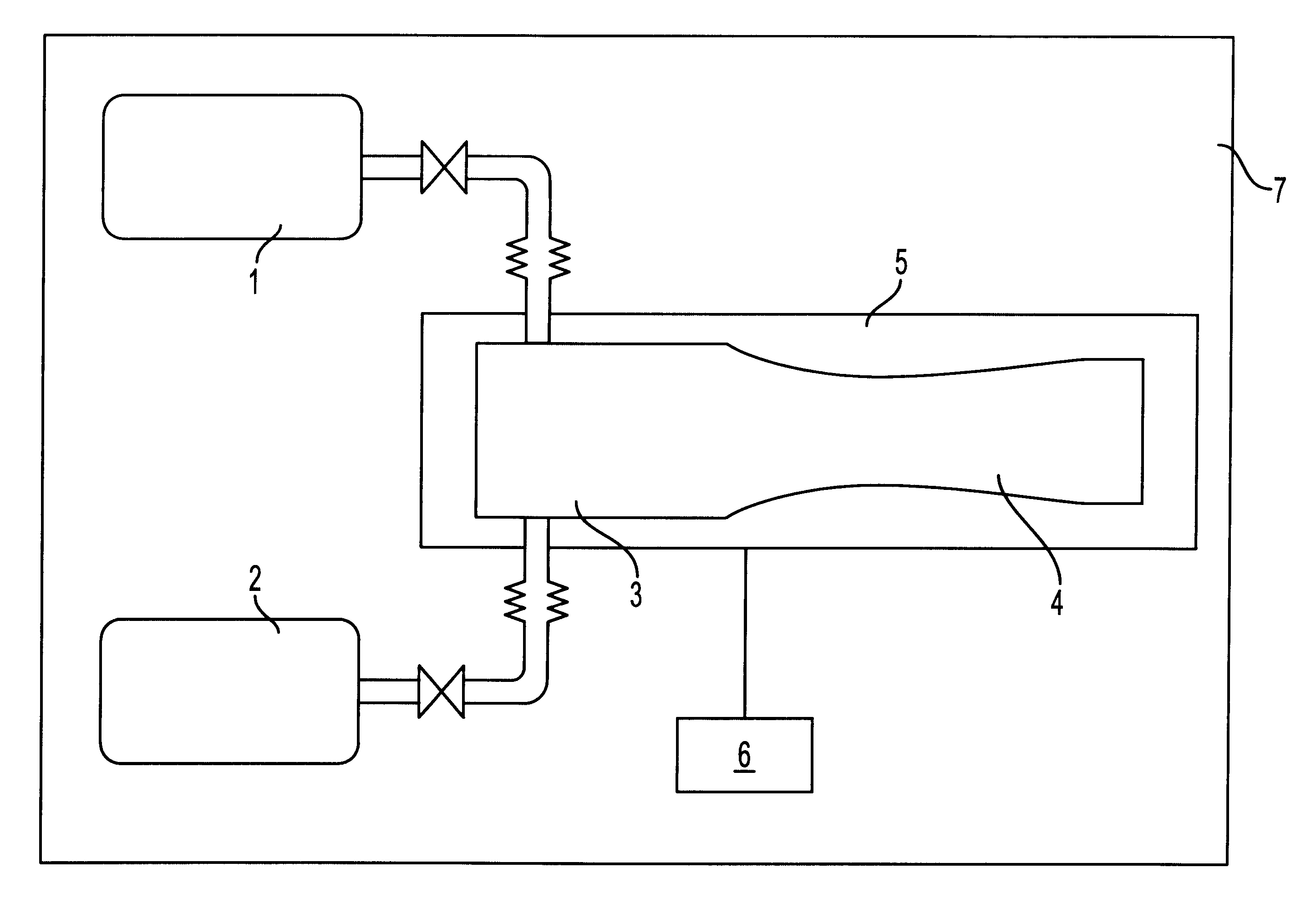
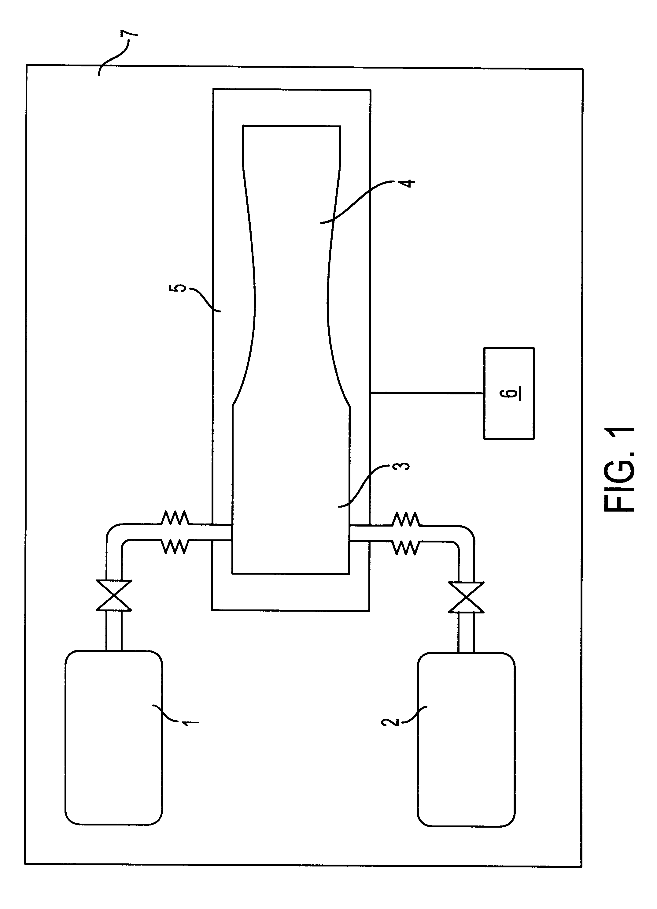
A fire extinguishing method can be effected with the help of a device, a functional schematic view of which is illustrated in FIG. 1.

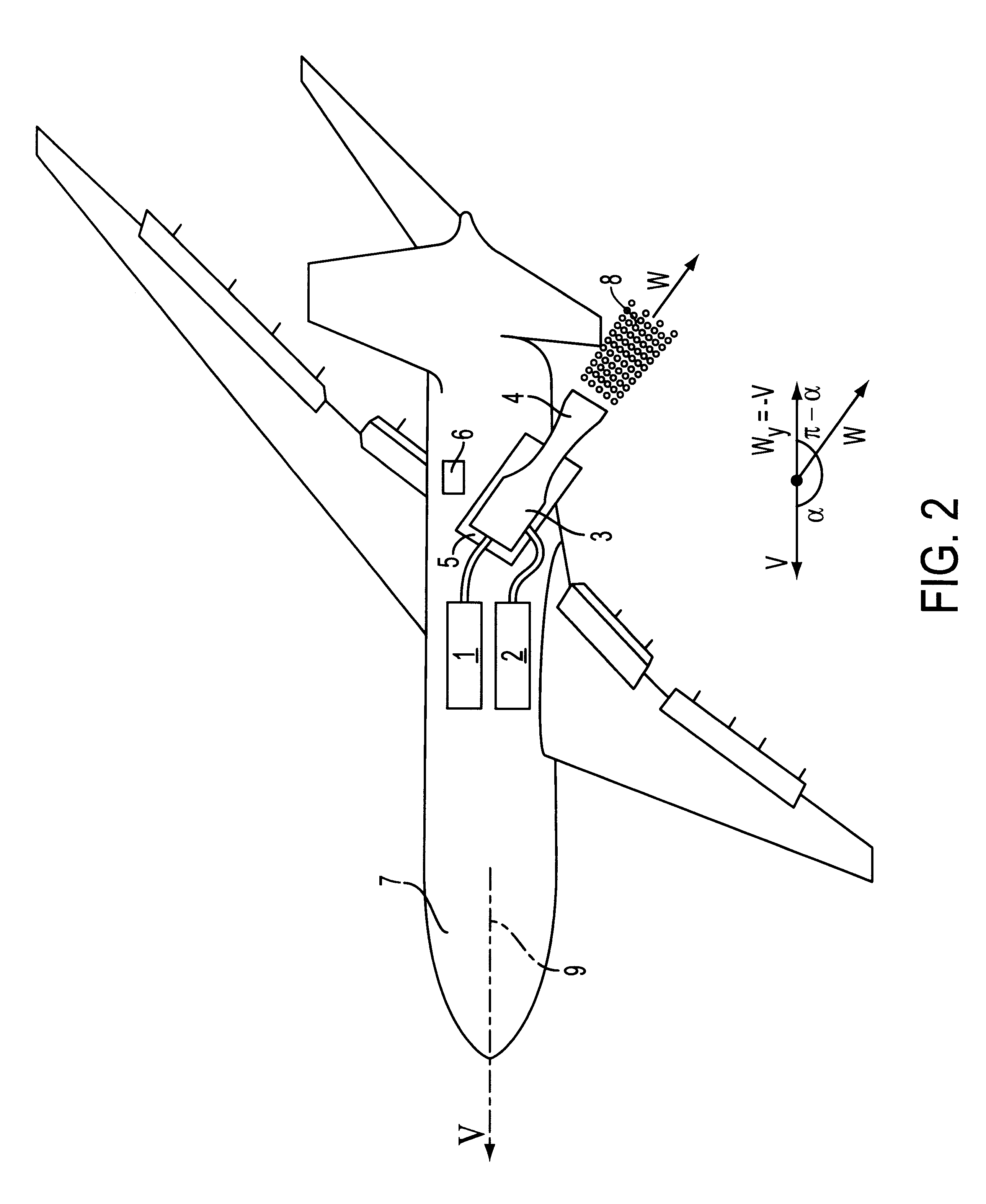
A fire extinguishing device comprises a liquid supply system 1 meant for fire extinguishing, a gas supply system 2, a liquid and gas mixing chamber 3, a gas-dynamics nozzle 4, a controllable platform 5 with a displacement mechanism, on which a nozzle 4 with a chamber 3 are installed, a control system 6, which are placed on board an aircraft, e.g. airplane 7, in its aft part (see FIG. 2).

The nozzle 4 with the help of a moving platform 5 is oriented in the desired direction. For complete compensation of disturbing aerodynamic forces the inclination angle of gas-droplet stream 8 speed vector W with respect to the aircraft speed vector V is chosen from the condition of total jet impulse value minimization along its flight trajectory in the direction of disturbing force effects. In the case considered the speed vector V coincides with the axis of symmetry 9...


PUM


Abstract

The present invention comprises supplying a liquid onto the source of a fire from an aircraft (7), wherein said liquid is supplied in the form of gas-droplet stream (8) obtained by dispersion in a gas flow and by acceleration of the dual-phase flow in a gas-dynamics nozzle (4). The pressure at the inlet of the nozzle (4) as well as the relative concentration of liquid in the dual-phase flow are selected according to conditions enabling the formation of a dual-phase low-dispersion and high-speed flow which has a high extinguishing-substance concentration and remains stable when submitted to interference.The fire-extinguishing device of the present invention comprises a liquid supply system (1), a gas supply system (2), a mixing chamber (3) for the gas and the liquid as well as a gas-dynamics nozzle (4), wherein all these members are is arranged onboard on aircraft (7). The gas-dynamics nozzle supplies the liquid towards the area of the fire source and is connected to a vessel through a duct. The mixing chamber (3) is further provided with a liquid dispersion system.

Description

FIELD OF THE ARTA group of inventions is related to fire fighting techniques and aviation engineering, namely, it concerns fire fighting aviation means applied for extinguishing the fire sites on the inaccessible territories, in multistory buildings or in cases when the supply of fire extinguishing means is required from rather a great height.PRIOR STATE OF THE ARTAt present are known different methods and devices to extinguish fires by way of releasing liquid from special vessels on board an aircraft, preferably airplanes.Thus, e.g., from Patent PL 127704 a device is known designed for fire extinguishing with the help of airplanes, which houses vessels for liquid storage, two liquid drain throats, an air inlet connected with the upper part of the vessels and controlled drain valves.Utilization of two holes for liquid drain gives and opportunity to have different liquid consumption depending on combination of valve openings. This allows, in its turn, to extinguish fire on a large te...

Claims


Application Information

Patent Timeline
Patent Type & Authority Patents(United States)
IPC IPC(8): A62C39/00A62C3/00A62C3/02B64D1/16B64D1/00A62C31/00A62C99/00
CPCA62C3/0207A62C99/0072B64D1/16
Inventor ZUEV, JURY VLADIMIROVICHKARPYSHEV, ALEXANDR VLADIMIROVICHLEPESHINSKY, IGOR ALEKSANDROVICH
Owner NAUCHNO ISSLEDOVATELSKY INSTITUT NIZKIKH TEMPERATUR PRI MAI
Why Eureka
Try Eureka