Welding gun and methods conducted using the same

a welding gun and intelligent technology, applied in the direction of resistance electrode holders, electrode features, manufacturing tools, etc., can solve the problems of lowering responsibility, affecting the accuracy of conventional methods,

Inactive Publication Date: 2001-11-06
TOYOTA JIDOSHA KK
View PDF16 Cites 34 Cited by
  • Summary
  • Abstract
  • Description
  • Claims
  • Application Information

AI Technical Summary

Benefits of technology

Another object of the present invention is to provide a welding gun which allows an arm supporting a fixed side welding tip to be decreased in size and rigidity, and to provide various kinds of control methods conducted using the welding gun.
In the ninth method that is a method of controlling a pressing force of welding conducted using the welding gun, both the fixed side sensor and the moving side sensor are used. The driving device for the moving side portion may be a servo motor or may be an air cylinder. In the ninth method, controlling the pressing force is conducted based on information about positions x.sub.1 and x.sub.1 ' of the moving side welding tip and the fixed side welding tip when the welding tips reach the contacting points with a workpiece (at that time the electric current of the motor for driving the moving side welding tip suddenly increases). More particularly, the differentials between the objective positions x.sub.T and x.sub.T ' of the moving side welding tip and the fixed side welding tip and the contacting positions x.sub.1 and x.sub.1 ' are calculated, respectively. When differentials exist, which means that the workpieces have a clearance therebetween, the pressing force continues to be imposed on the workpiece based on gains proportional to the differentials. Due to this pressing, the workpieces are pressed and the clearance between the workpieces is eliminated. When the differentials becomes zero or the differentials do not exist, the arriving positions x.sub.2 and x.sub.2 ' of the moving side welding tip and the fixed side welding tip are obtained from the currently detected positions x.sub.1 and x.sub.1 ' of the moving side welding tip and the fixed side welding tip. Then, the pressing force P.sub.o required for the welding tips to reach the respective arriving points is calculated. The pressing force P.sub.o is a force imposed on the workpieces in order to eliminate the clearance between the workpieces and therefore is a spring back force of the workpieces. A pressing force P.sub.1 necessary for welding is further added to the pressing force P.sub.o, and the total pressing force P.sub.o of P.sub.1 and P.sub.T is imposed on the workpieces. Due to this operation, even if a clearance exists between the workpieces, the pressing force P.sub.1 necessary for welding can be imposed on the workpieces, so that a spot welding of a high quality having a sufficient pressing force can be performed.

Problems solved by technology

However, there are the following problems with the above-described conventional method for controlling a welding gun.
First, since a moving side portion of the welding gun including the moving side electrode tip and the servo motor for driving the moving side electrode tip is provided with a speed reducer, a mechanical impedance of the moving side portion is greater and dynamically harder than that of a fixed side portion of the welding gun.
As a result, the responsibility is lowered, so that it is difficult to obtain an accurate response with the conventional method, in which the welding gun is controlled based on an output of the encoder.
Second, since the rigidity of an arm supporting the fixed side electrode tip is increased so that the mechanical impedance of the fixed side portion including the fixed side electrode tip and the arm is nearly equal to the mechanical impedance of the moving side portion, the size and the weight of the arm is large, which causes the welding gun to be increased both in size and weight.
When the expansion quantity of the welding portion during welding does not reach the predetermined value even though the welding electric current is increased which may be caused by dust or the like adhering to the workpiece or by a malfunction of the apparatus re-welding is conducted, because it may work in the case of the adhesive dust or the like.
With respect to control of the welding gun, since a very small change in the expansion quantity has to be detected, it is difficult in the detected quantity and responsibility to perform an accurate control of the expansion quantity by using the conventional servo motor encoder.
In the control, since a very small change in the gradient has to be detected, it is difficult in quantity and responsibility to perform an accurate control of the expansion quantity by using the conventional servo motor encoder.
However, when the thermal expansion quantity decreases during pressing, which means that some welding expulsion is generated, the welding electric current is decreased.

Method used


Image

  • Welding gun and methods conducted using the same
  • Welding gun and methods conducted using the same
  • Welding gun and methods conducted using the same

Examples


Embodiment Construction

FIGS. 1-5 illustrate a welding gun according to an embodiment of the present invention. FIGS. 6-21 illustrate various kinds of methods conducted using the welding gun according to the embodiment of the present invention. The methods include, for example, a calibration method of a sensor, a confirmation method of a sensor operation, a control method of welding, and a managing method of welding data.

First, the welding gun according to the embodiment of the present invention will be explained with reference to FIGS. 1-5.

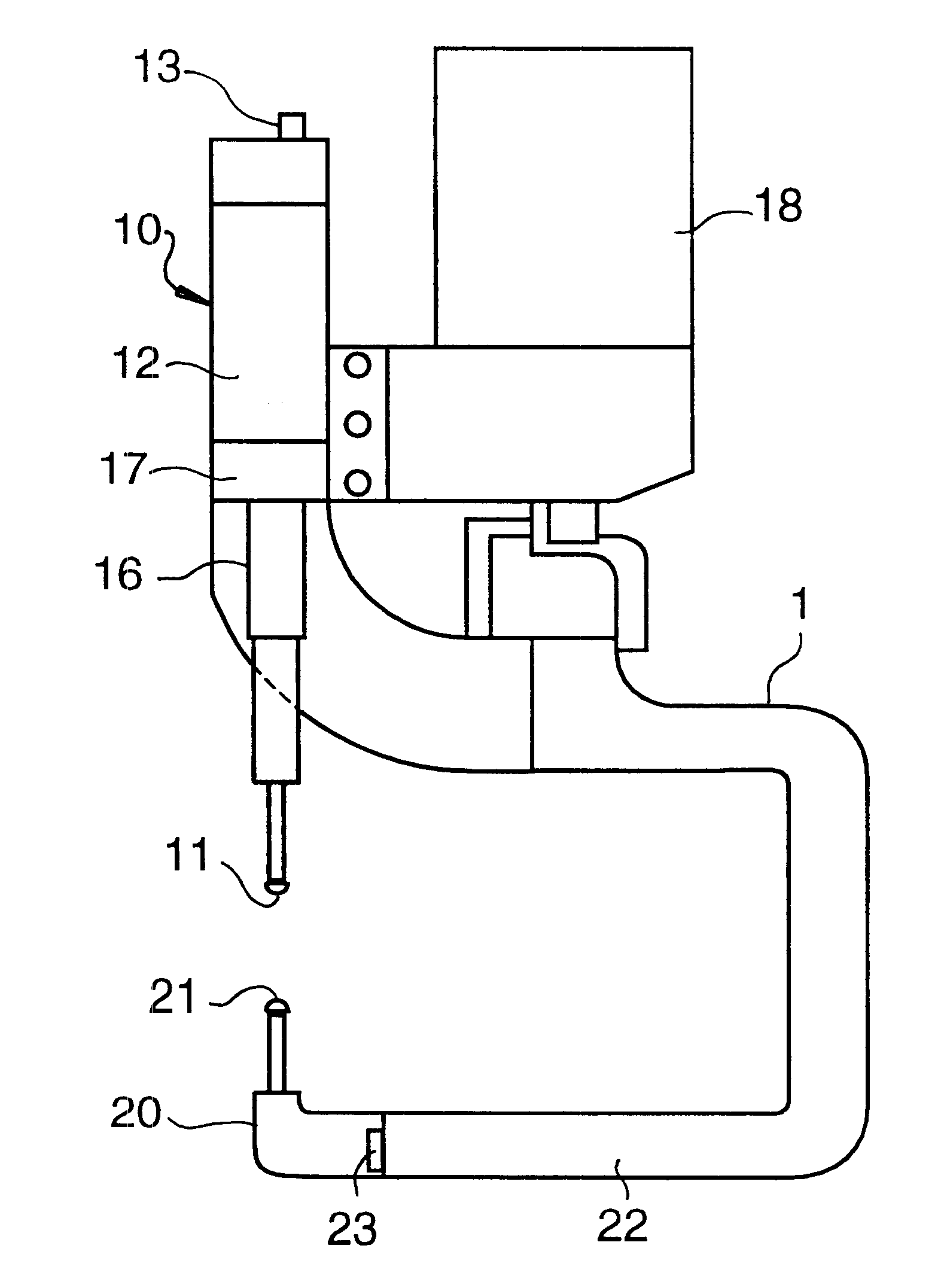
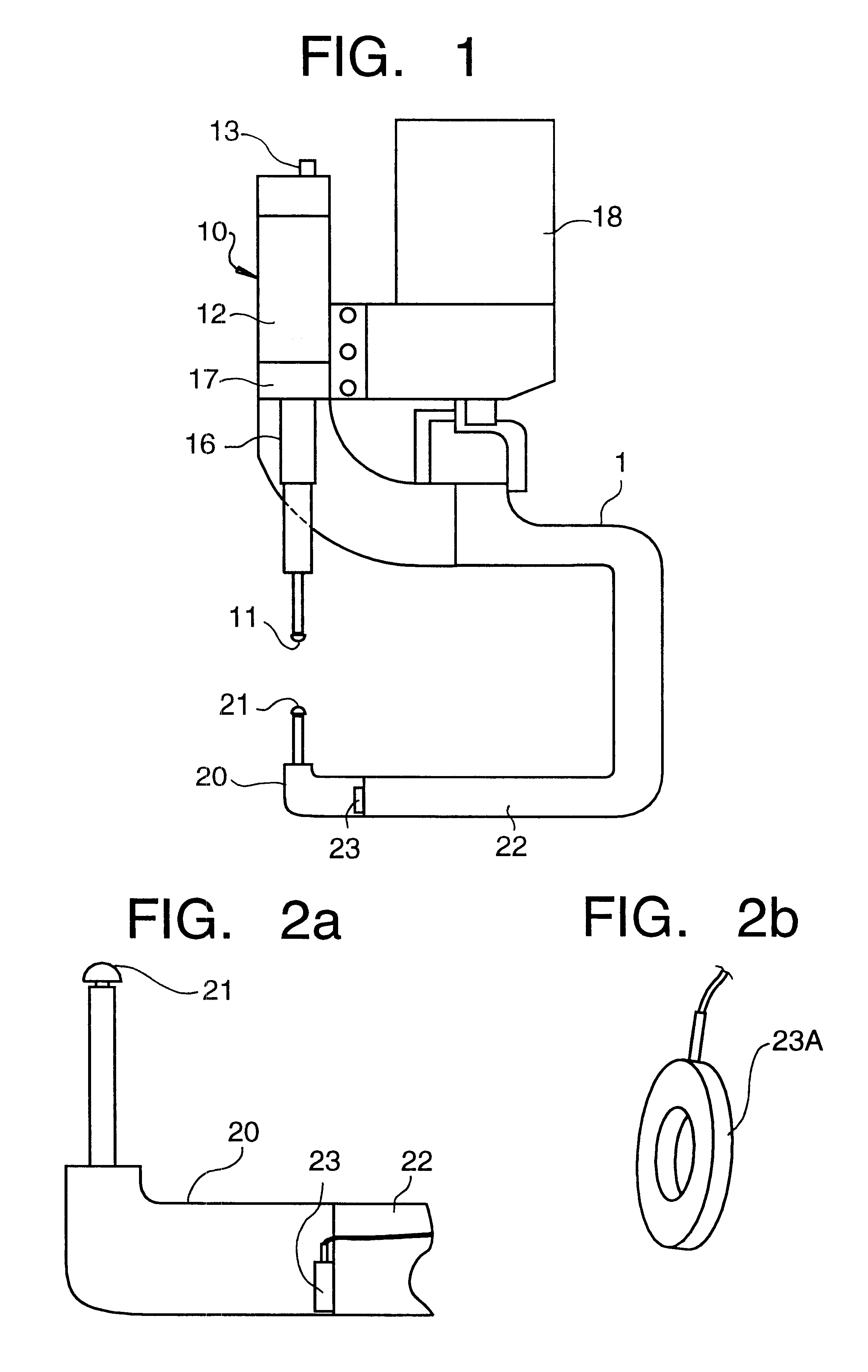
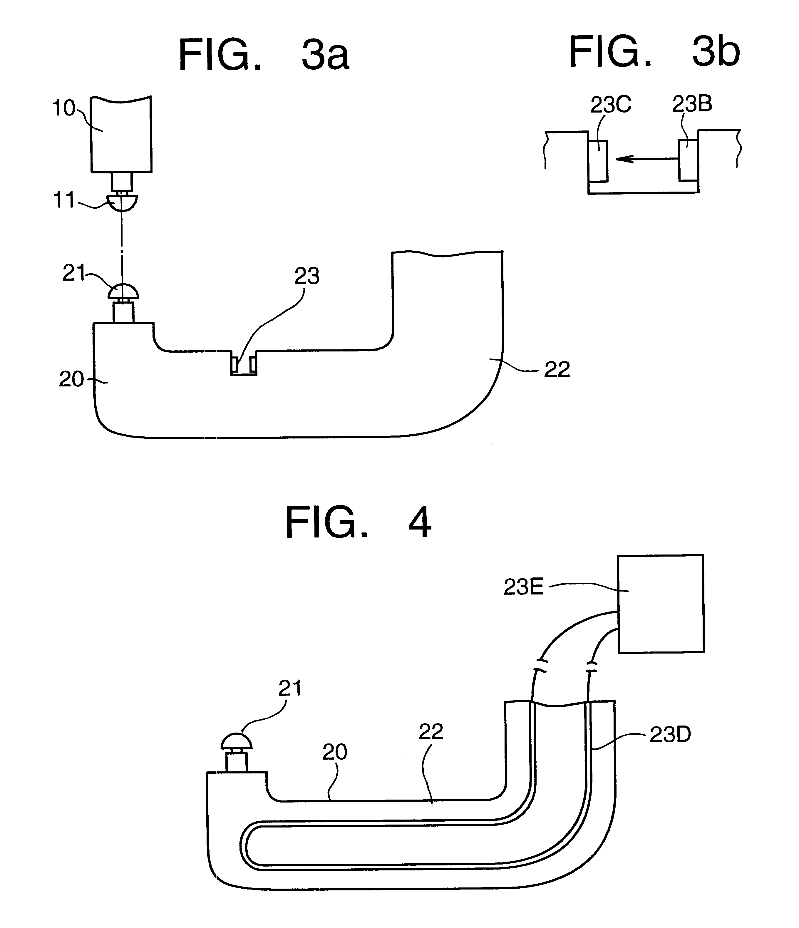
As illustrated in FIG. 1, the welding gun 1 includes a moving side portion 10 including a moving side welding tip 11 and a driving device 12 for driving the moving side welding tip 11, and a fixed side portion 20 including a fixed side welding tip 21 and an arm 22 supporting the fixed side welding tip 21.

A fixed side sensor 23 is disposed in the fixed side portion 20 for detecting at least one of a position of the fixed side welding tip 21 and a pressing force imposed o...


PUM

PropertyMeasurementUnit
compression stressaaaaaaaaaa
pressing forceaaaaaaaaaa
mechanical impedanceaaaaaaaaaa

Abstract

An intelligent welding gun is provided with a fixed side sensor in a fixed side portion. The mechanical impedance of the fixed side portion is kept small, which permits the mechanical impedance to be set in a range where the fixed side sensor can effectively detect at least one of a position of a fixed side welding tip and a pressing force imposed on the fixed side welding tip. The fixed side sensor and a moving side sensor constitute a redundant sensor measurement system. Various kinds of methods conducted using the above welding gun include a method of calibrating a sensor (including calibration of a reference point and a gain), a control method of suppressing a welding expulsion, a re-welding feedback control method, a control method of a welding strength, a control method of reducing a clearance between workpieces, a method of correcting a welding robot track, and a method of managing a positional accuracy change at a welding point.

Description

1. Field of the InventionThe present invention relates to an intelligent welding gun provided with a sensor, and various kinds of methods conducted by using the welding gun including a calibration method of a sensor, a control method of welding (which includes, for example, a control method of a pressing force, a feedback control method of re-welding, a control method of welding strength, a control method of suppressing the generation of a weld expulsion, and a control method of a track of a welding robot), and a managing method of a change in a positional accuracy of a welding point.2. Description of Related ArtJapanese Patent Publication No. 10-94882 discloses a method for controlling a pressing force of a welding gun. In the method, a small quantity of an elastic displacement, generated in a fixed side electrode tip when a moving side electrode tip is driven to contact the fixed side electrode tip and further driven to press the fixed side electrode tip, is detected by an encoder...

Claims


Application Information

Patent Timeline
Patent Type & Authority Patents(United States)
IPC IPC(8): B23K11/10B23K11/31B23K11/25B23K11/30B23K11/24
CPCB23K11/10B23K11/253B23K11/311B23K11/315
Inventor SUITA, KAZUTSUGU
Owner TOYOTA JIDOSHA KK
Why Eureka
Try Eureka