
Byte code instrumentation

a technology of instrumentation and byte code, applied in the field of computer software, can solve the problems of inefficient manual instrumentation, add time and effort to the debugging process, improper operations to be performed by the software without being detected,

Inactive Publication Date: 2001-11-06
BORLAND
View PDF14 Cites 260 Cited by
  • Summary
  • Abstract
  • Description
  • Claims
  • Application Information

AI Technical Summary

Problems solved by technology

Specifically, since many run time errors are the result of improperly accessing or using memory (e.g., writing beyond an array's boundaries, not freeing dynamically allocated memory, etc.), then instrumentation may be used to supplement memory accessing portions of the software with additional software that monitors memory accesses and provides an indication when it appears that an improper access has occurred.
However, such manual instrumentation is often inefficient for a number of reasons.
However, once the programmer has identified possible sources of error, it may be more straight-forward to simply examine the potentially errant code and fix the error rather than perform the additional steps associated with adding source code instrumentation statements.
In addition, manually adding source code instrumentation statements requires repeated recompiling of the source code before execution, which adds time and effort to the debugging process.
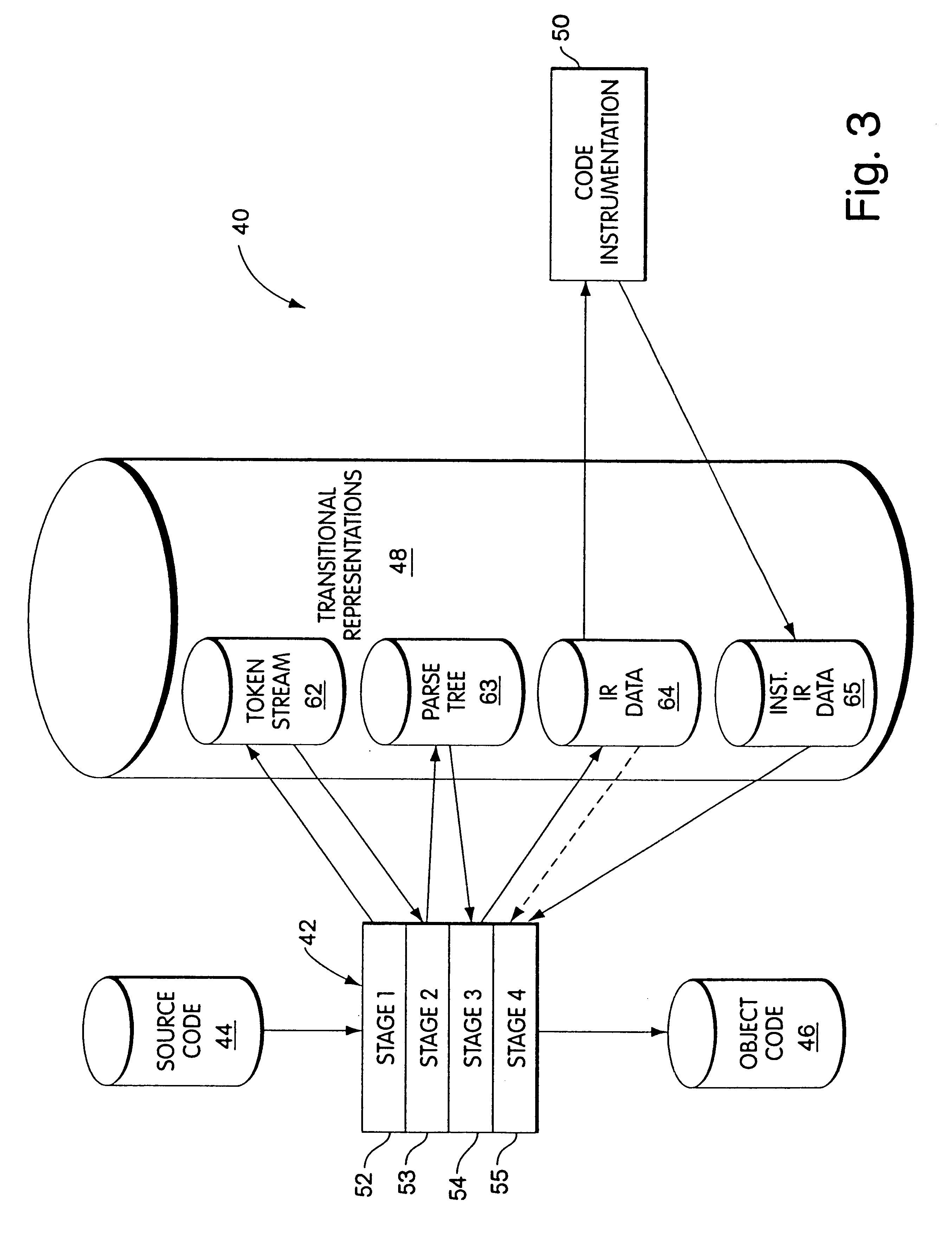
However, since the contents of the parse tree depend upon the particular source programming language used, the system disclosed in the '696 patent is also source dependent.
However, since the system disclosed in the Hastings patents involves modifying object code, then the system is target dependent in that it may only be configured to work with object code that executes a particular target processor's native language.
In addition, monitoring program memory accesses by maintaining the status of program memory locations allows some improper operations to be performed by the software without being detected.

Method used


Image

  • Byte code instrumentation
  • Byte code instrumentation
  • Byte code instrumentation

Examples


Embodiment Construction

)

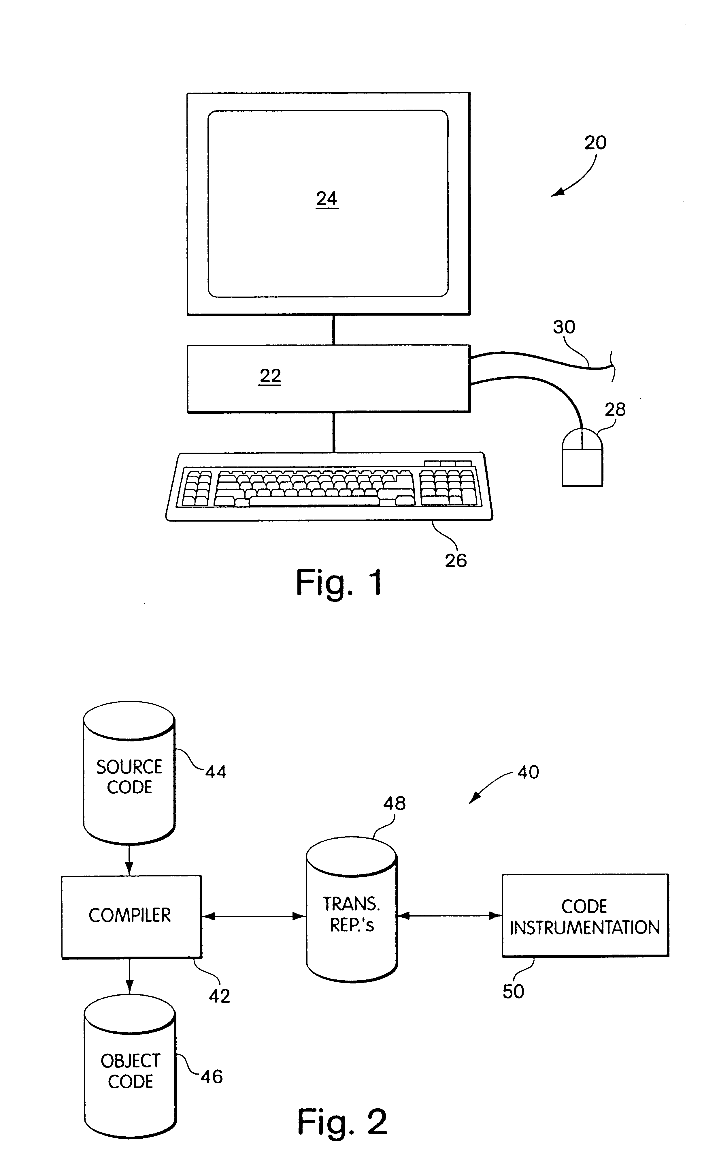
Referring to FIG. 1, a computer system 20 includes a processor 22, a display unit 24, a keyboard 26 and (optionally) a mouse input device 28. The user provides input to the processor 22 via the keyboard 26 and the mouse 28 and views output from the processor 22 via the display unit 24. The computer system may be a model P5-166 manufactured by Gateway Computer of Sioux City, S. Dak.

The computer system 20 may include a connection 30 to a conventional computer network (not shown), such as the Microsoft NT network. The computer system 20 may receive data and / or other network services, in a conventional manner, through the connection 30 to the network. The processor 22 may include conventional local storage or may use conventional storage available on the network wherein the processor 22 sends and receives data to and from the network via the network connection 30. The computer system 20 may use a combination of local storage and network storage in a conventional manner. In the discussi...


PUM


Abstract

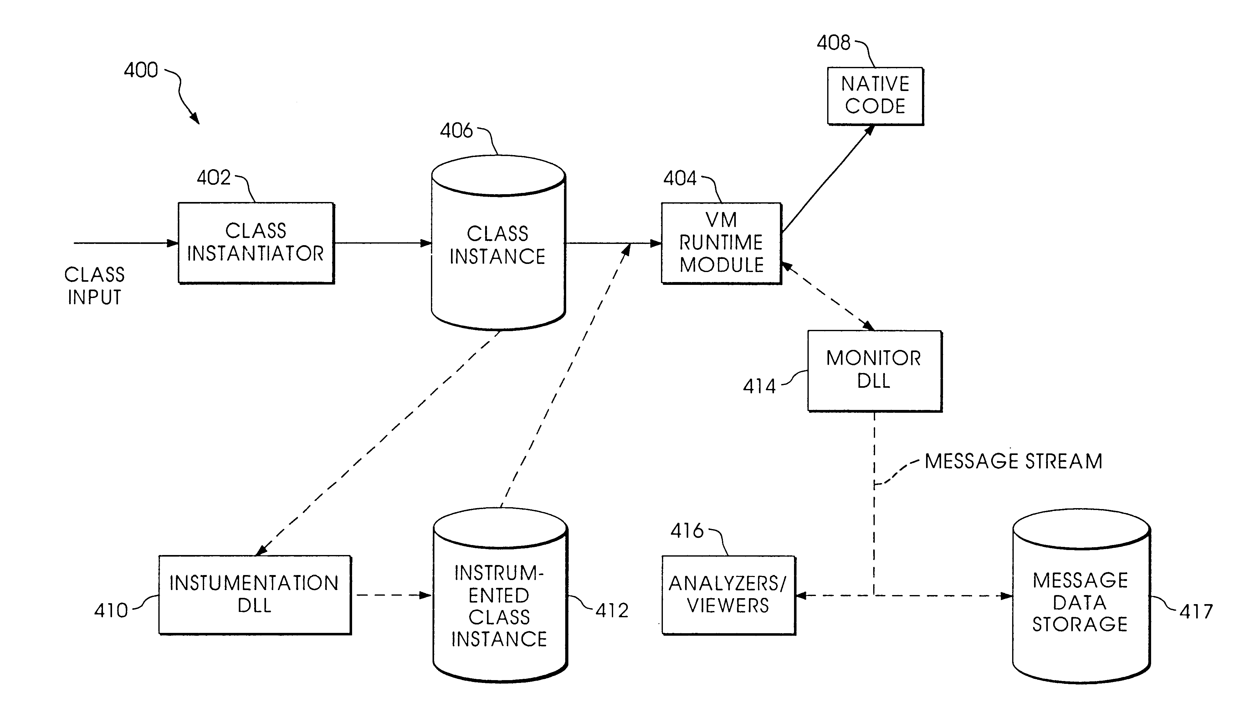
Instrumenting a computer program to provide instrumented byte code includes examining the byte code, selecting portions of the byte code for instrumentation, and instrumenting the portions to provide instrumented byte code. Selecting the portions may include choosing portions of the byte code corresponding to method entry, method exit, a throw, a method call, or a new line number. Instrumenting a portion of the byte code corresponding to a method call may include instrumenting a local line number of source code corresponding to the byte code being instrumented. Instrumenting the portions may include adding calls to instrumentation runtime functions that pass parameters indicative of the portions being instrumented. At least one of the parameters that is passed may include a line number of the source code corresponding to the portion being instrumented or a object pointer for the method corresponding to the portion being instrumented. Data from instrumentation may be passed via a message stream that is viewed as the data is being generated and / or stored.

Description

1. Field of the InventionThis application relates to the field of computer software and more particularly to the field of computer software for instrumentation of code in order to facilitate debugging.2. Description of Related ArtCode instrumentation is performed by adding statements to software in order to monitor performance and operation of the software during run time. Code instrumentation is sometimes used to facilitate debugging of run time errors relating to memory accesses. Specifically, since many run time errors are the result of improperly accessing or using memory (e.g., writing beyond an array's boundaries, not freeing dynamically allocated memory, etc.), then instrumentation may be used to supplement memory accessing portions of the software with additional software that monitors memory accesses and provides an indication when it appears that an improper access has occurred.Instrumentation may be performed manually by having the programmer insert source code statements...

Claims


Application Information

Patent Timeline
IPC IPC(8): G06F11/36
CPCG06F11/3612G06F11/3624G06F11/3636G06F11/3644G06F11/3466G06F2201/865G06F8/41G06F9/45516
Inventor ANGEL, DAVID J.KUMOREK, JAMES R.MORSHED, FAROKHSEIDEL, DAVID A.
Owner BORLAND
Learn More