Vehicle air induction system

Inactive Publication Date: 2001-11-13
FUEL MANAGEMENT
View PDF12 Cites 35 Cited by
  • Summary
  • Abstract
  • Description
  • Claims
  • Application Information

AI Technical Summary

Problems solved by technology

During periods of extremely hot or cold weather conditions, fuel consumption increases.
These air filters, which are located eithe

Method used


Image

  • Vehicle air induction system
  • Vehicle air induction system
  • Vehicle air induction system

Examples


Embodiment Construction

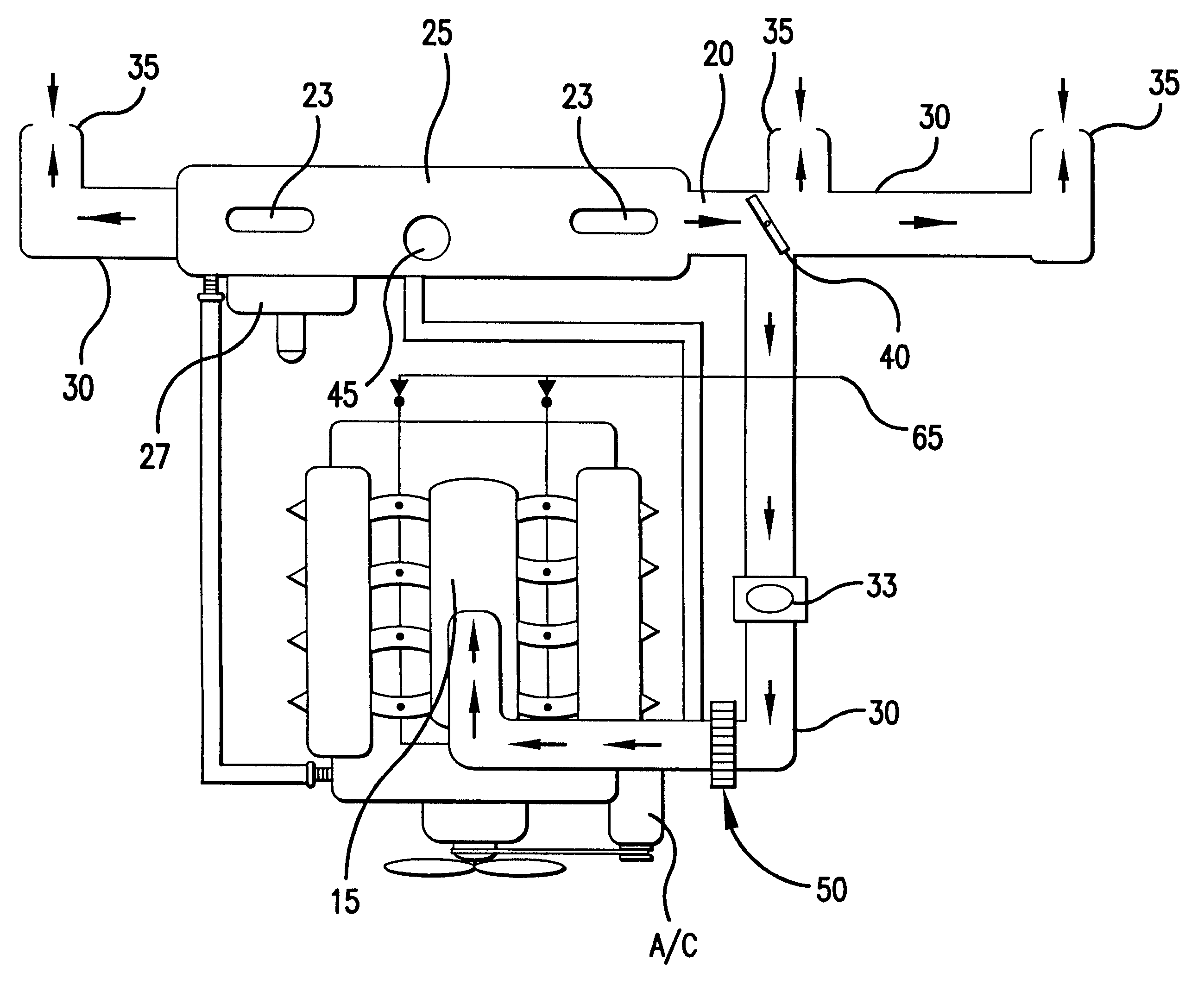
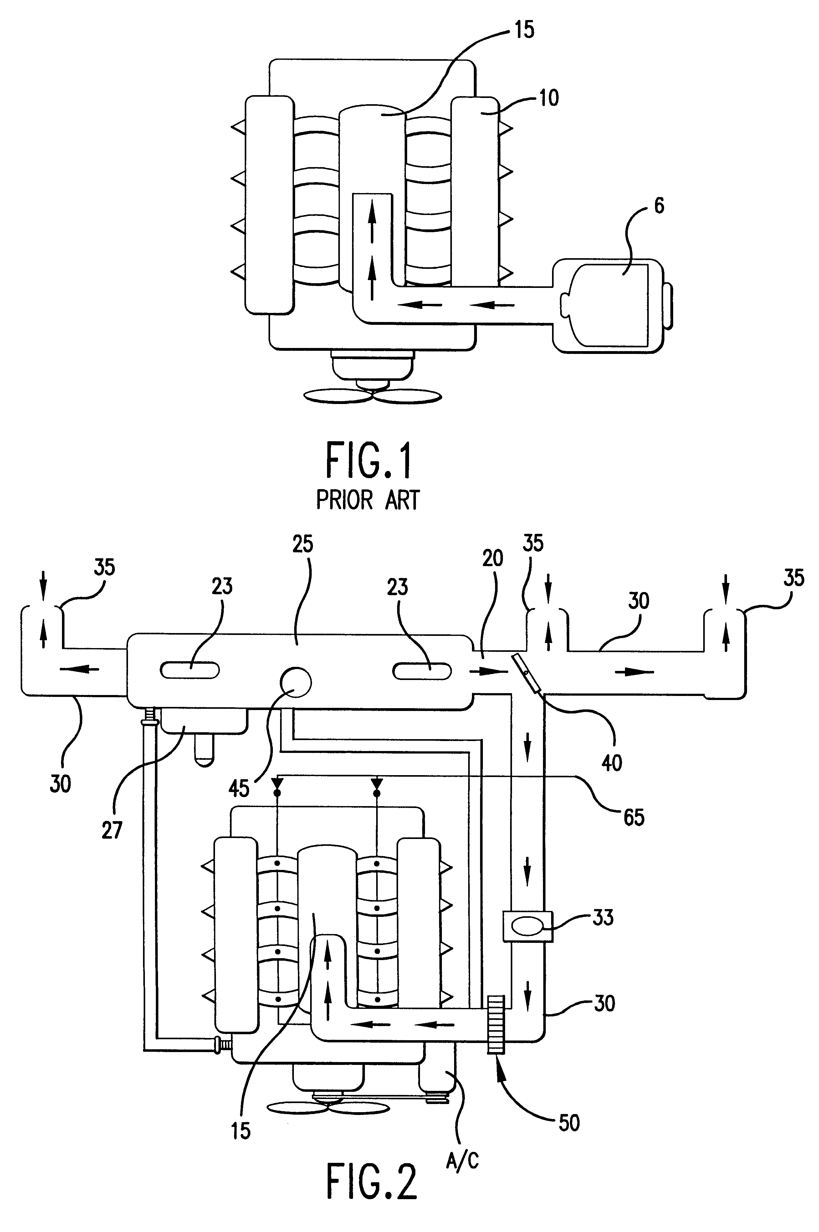
FIG. 1 shows a prior art air induction system wherein air flows from ambient and travels through an air filter 6 and into an air induction manifold 15 before entering engine 10. As shown in FIG. 2, the air induction system according to one preferred embodiment of this invention comprises an alternative system for providing air to air intake manifold 15 of engine 10.

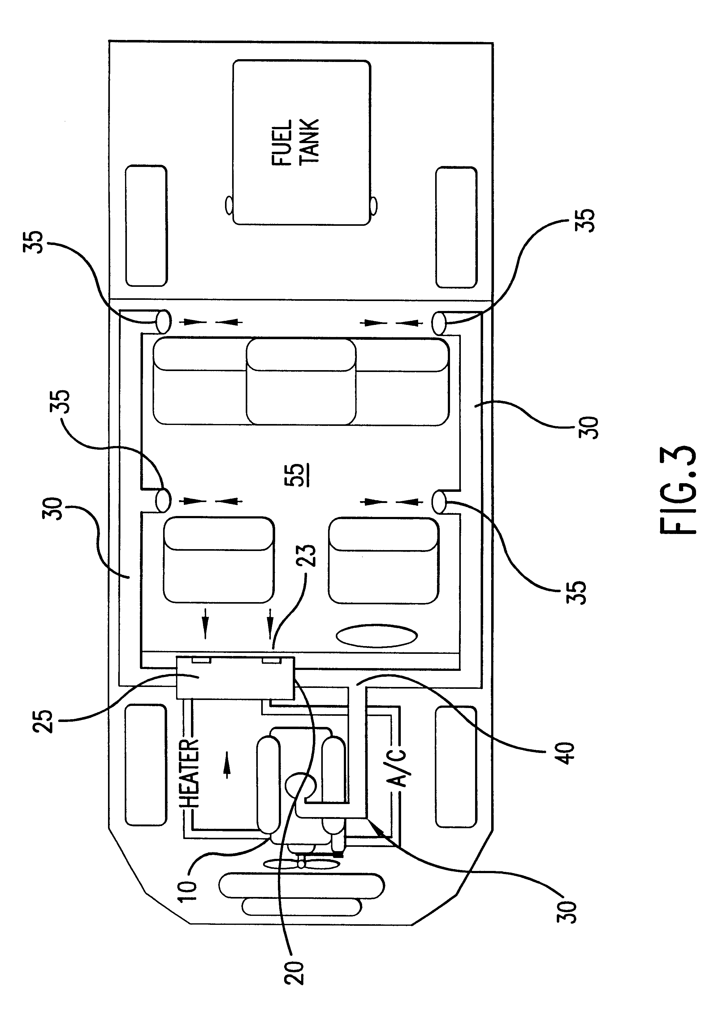
According to one preferred embodiment of this invention, as shown in FIGS. 2 and 3, one or more plenum outlets 20 are positioned within HVAC plenum 25 within the vehicles HVAC system. Fresh and / or recirculated air inlets 23 are necessarily required in conventional HVAC plenums 25. Plenum outlets 20 are preferably located in HVAC plenum 25 upstream of HVAC fan 27, shown in FIG. 2, that forces air into passenger compartment 55.

One or more interior air inlets 35 are preferably positioned within passenger compartment 55. Interior air inlets 35 may be positioned in existing internal vent locations or positioned in new location...


PUM


Abstract

This invention is an air induction system that enables an enhanced flow of temperature-controlled, magnetically influenced forced air to the air intake of internal combustion, turbine-type, and other engines having an air intake manifold. An interior air inlet is positioned in communication with a passenger compartment of the vehicle. Additionally, or alternatively, a plenum outlet is positioned in an HVAC plenum of the vehicle. An air supply duct extends between the interior air inlet and/or the plenum outlet and the air intake manifold supplies conditioned air to the air intake manifold. Performance may be enhanced with the positioning of magnets and/or an air diverter valve into the system. As a result of the enhanced flow of magnetically influenced air and the more steady state of the temperature of the inducted air, fuel consumption and air emissions levels are reduced.

Description

1. Field of the InventionThis invention relates to an air induction system that enables an enhanced flow of temperature-controlled, magnetically influenced forced air to the air intake of internal combustion, turbine-type, and other engines.2. Description of Related ArtConventional air induction systems have an air filter assembly located in or outside of the engine compartment of the vehicle. An air filter is required at the air intake manifold to filter air as it enters the engine. Unfiltered inducted air generally contains dirt particles and other contaminants and has a temperature equal to or greater than the ambient temperature outside the vehicle. During periods of extremely hot or cold weather conditions, fuel consumption increases. Air filters that are currently being used today are made of rigid tubing, have a paper air filter element, and are enclosed in a restrictive housing. These air filters, which are located either inside or outside the engine compartment, place obstr...

Claims


Application Information

Patent Timeline
IPC IPC(8): F02B29/04F02B29/00F02M27/00F02M27/04F02M35/16F02M35/00F02M31/125F02M35/12F02M31/02F02M31/10F02M31/06
CPCF02B29/0437F02B29/0481F02B29/0493F02M27/045F02M31/06F02M31/10F02M31/125F02M35/10019F02M35/10118F02M35/10242F02M35/161F02M35/1211F02M35/1216F02M35/1233F02M35/1272F02B29/0475Y02T10/146Y02T10/126Y02T10/12
Inventor DEGRAZIA, JR., TOREY W.RAJSKI, MARGARET
Owner FUEL MANAGEMENT
Why Eureka
Try Eureka