Systems and methods for differential heating of exhaust catalysts

Active Publication Date: 2016-09-01
FORD GLOBAL TECH LLC
View PDF2 Cites 12 Cited by
  • Summary
  • Abstract
  • Description
  • Claims
  • Application Information

AI Technical Summary

Benefits of technology

[0002]Embedding electrical heaters into exhaust catalysts enhances device performance. Specifically, increasing heater thermal output allows the catalyst temperature to be increased to a point that increases the exhaust efficiency, particularly during periods of low temperature operation. Segmentation of catalyst s

Problems solved by technology

In this way, control of exhaust heating may become very difficult, particularly in systems with

Method used


Image

  • Systems and methods for differential heating of exhaust catalysts
  • Systems and methods for differential heating of exhaust catalysts
  • Systems and methods for differential heating of exhaust catalysts

Examples


Embodiment Construction

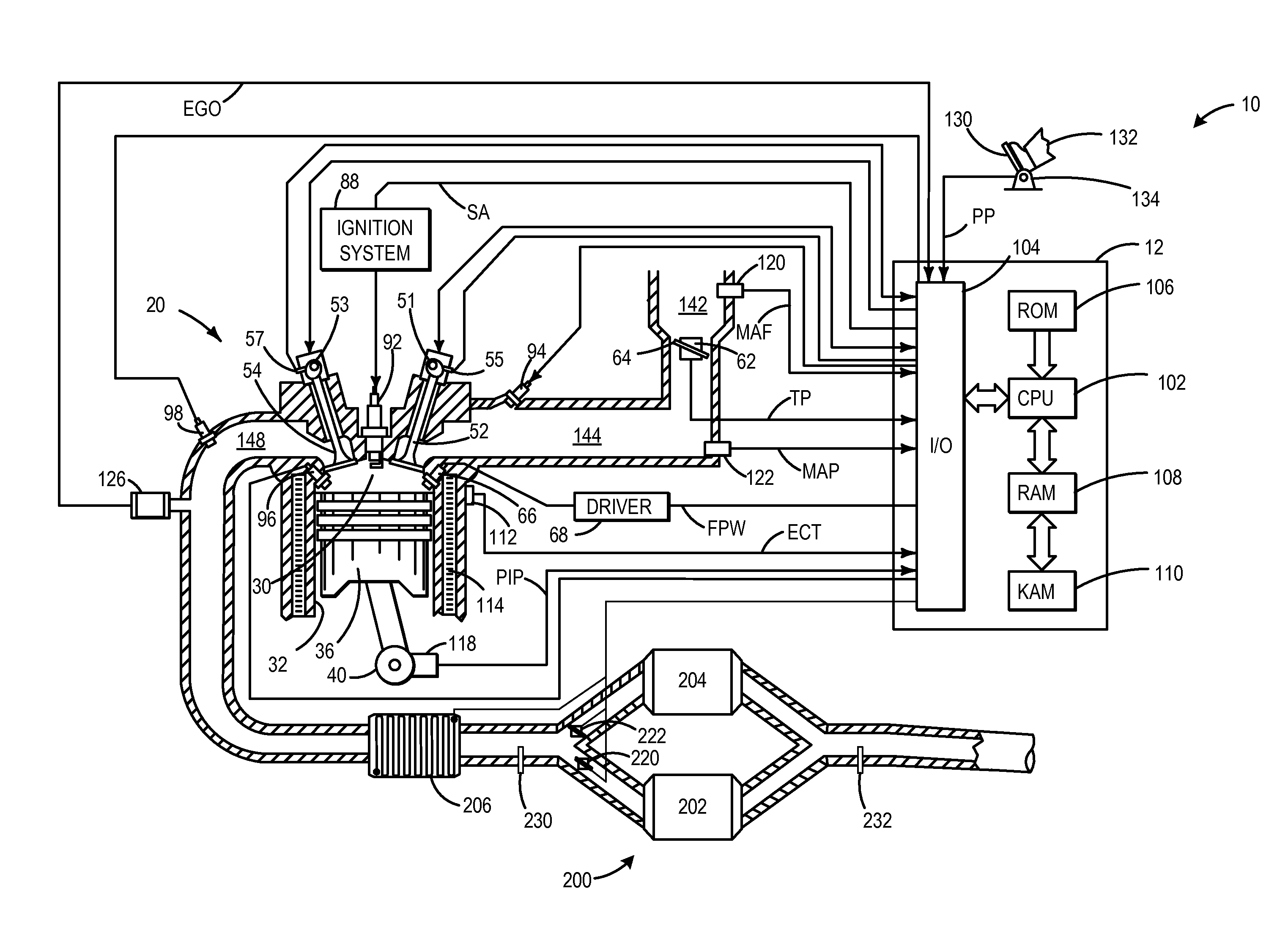
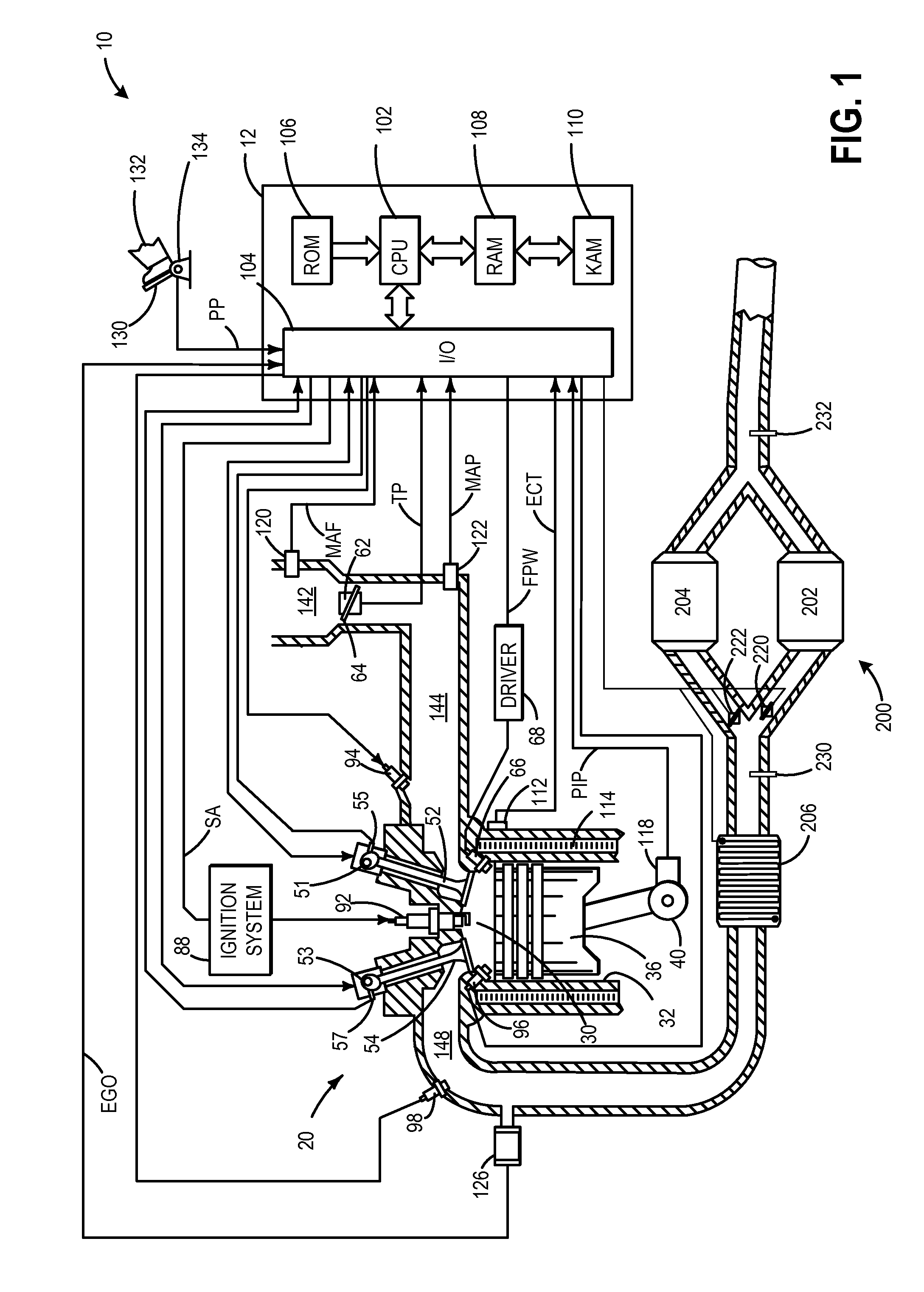
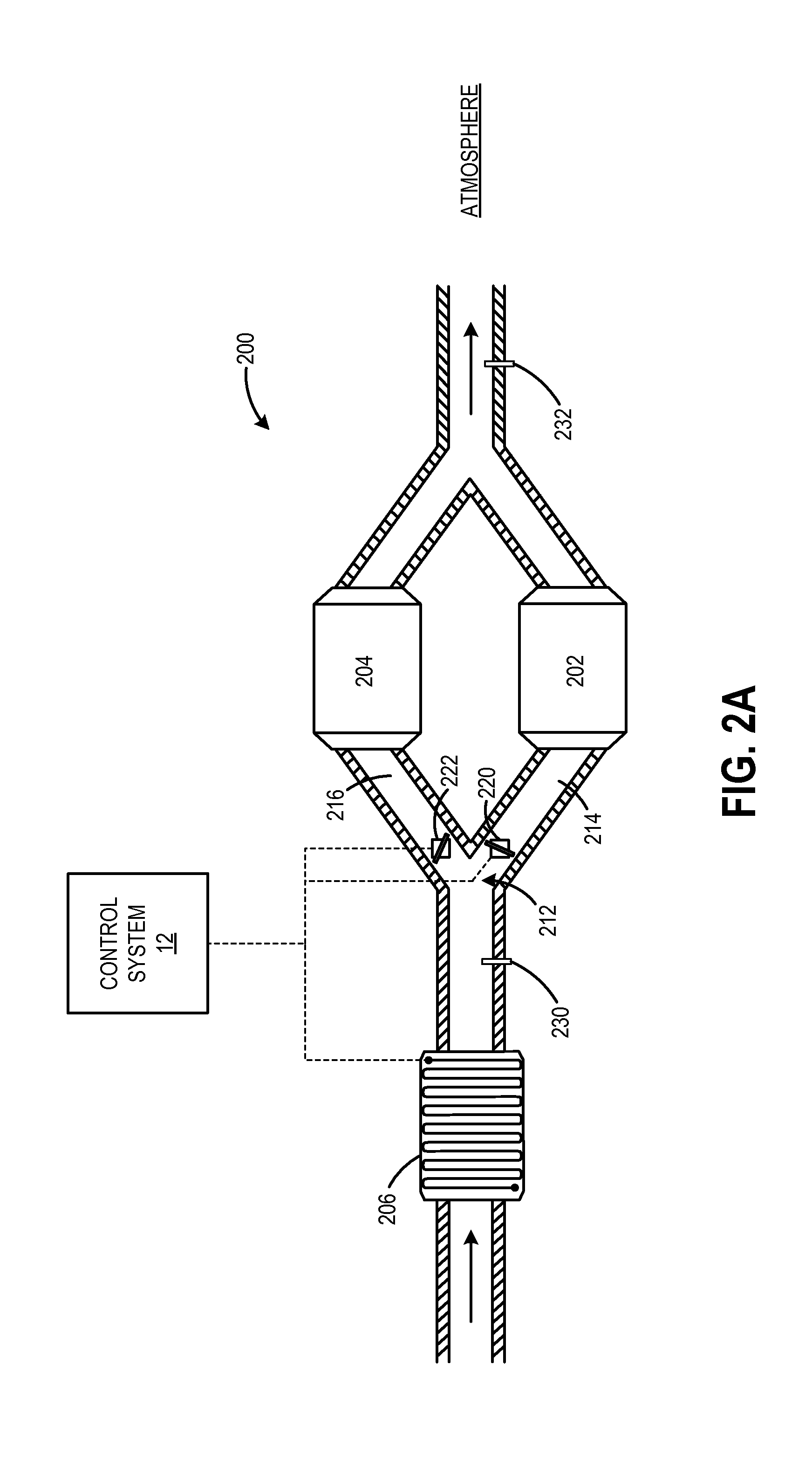
[0015]The following description relates to exhaust aftertreatment systems and methods for enhancing exhaust gas treatment to reduce emissions therefrom more efficiently. In one example, an exhaust gas aftertreatment system comprises a first catalyst positioned in a first exhaust pathway arranged in parallel to a second catalyst positioned in a second exhaust pathway. FIG. 1 and FIGS. 2A-C illustrate one such arrangement. According to the present disclosure, the exhaust system is configured with an electrical heater positioned upstream of an exhaust branchpoint for heating the exhaust flow and differentially controlling catalyst substrate temperatures within two catalysts. As such, FIGS. 3 and 4 illustrate exemplary routines for adjusting the thermal output of an electrical heater while adjusting a valve position to adjust the flow distribution to each of the catalysts to selectively control the catalyst substrate temperature. Embodiments are also possible including a single valve in...


PUM


Abstract

Exhaust aftertreatment systems and methods are described for reducing emissions output therefrom. In one example, an exhaust gas aftertreatment system comprises a first catalyst downstream of a branchpoint in a first exhaust pathway, a second catalyst downstream of the branchpoint in a second exhaust pathway, an electrical heater positioned upstream of the branchpoint for heating the exhaust flow, a control unit for adjusting an exhaust heating current of the electrical heater, and a valve for adjusting a distribution of exhaust flow to the first and second catalyst, the control unit including instructions to adjust the valve responsive to a substrate temperature within one or more of the first and second catalysts. In this way, an exhaust system with increased efficiency across a range of operating temperatures is realized that reduces emissions and energy expended during usage.

Description


Claims


Application Information

Patent Timeline
IPC IPC(8): F01N3/20
CPCF01N3/2066F01N3/2013F01N3/208F01N9/00F01N2240/16F01N2410/03F01N2560/026F01N2900/1602F01N13/011Y02T10/12Y02T10/40F01N3/10F01N3/20B01D53/94
Inventor UPADHYAY, DEVESH
Owner FORD GLOBAL TECH LLC
Why Eureka
Try Eureka