Electronic device, control method for electronic device, recharge-rate estimating method for secondary battery, and charging control method for secondary battery

a technology of electronic devices and control methods, applied in the direction of electric winding, instruments, horology, etc., can solve the problems of waste of power, difficulty in providing the above positional relationship, and water tightness at the point of watertightness

Inactive Publication Date: 2001-11-13
CHAMIRAUX MANAGEMENT LLC
View PDF19 Cites 106 Cited by
  • Summary
  • Abstract
  • Description
  • Claims
  • Application Information

AI Technical Summary

Problems solved by technology

On that occasion, if charging, data transfer, etc. are performed through electrical contacts, a problem would occur in point of watertightness because the electrical contacts are exposed to the outside.
To provide the above positional relationship just by placing the portable electronic device in the station is however difficult due to, e.g., the accuracy with which the coils are disposed in the station and the portable electronic device.
Further, if charging is carried out in spite of the portable electronic device being not placed in the station, a high-frequency signal would be uselessly applied to the coil on the station side, thus resulting in wasteful consumption of power.
A mechanism of mechanically detecting the positional relationship between both the coils through contacts, for example, raises a problem in point of watertightness as mentioned above.
Meanwhile, when a secondary battery is charged up to a desired capacity in the above arrangement, charging the secondary battery beyond the desired capacity is wasteful consumption of power and is uneconomical.
Furthermore, there is a risk that charging beyond the r

Method used


Image

  • Electronic device, control method for electronic device, recharge-rate estimating method for secondary battery, and charging control method for secondary battery
  • Electronic device, control method for electronic device, recharge-rate estimating method for secondary battery, and charging control method for secondary battery
  • Electronic device, control method for electronic device, recharge-rate estimating method for secondary battery, and charging control method for secondary battery

Examples


first embodiment

[1.7] Modifications of First Embodiment

The above-described first embodiment can be modified as follows.

[1.7.1] First Modification

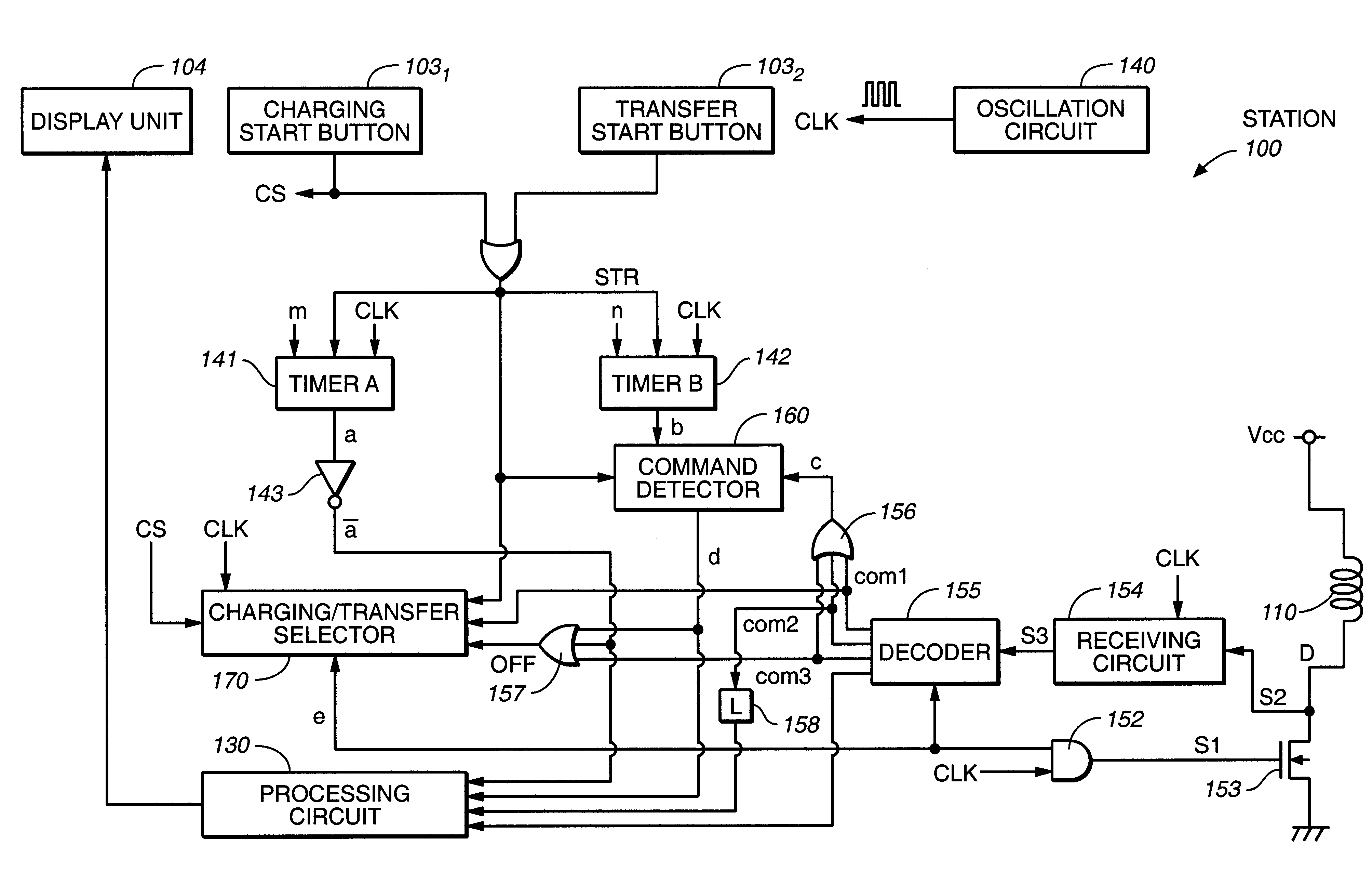
While in the first embodiment the data transfer is performed only in one direction from the electronic watch 200 to the station 100, it is a matter of course that data may be transferred in an opposite direction from the station 100 to the electronic watch 200. When data is transferred to the electronic watch 200, the station 100 executes modulation in accordance with the data to be transferred, whereas the electronic watch 200 executes demodulation in match with the modulation scheme. In such a case, well-known techniques can be used to execute the modulation and the demodulation.

[1.7.2] Second Modification

While in the first embodiment the position offset and the absence of the electronic watch are indicated by the display unit 104 provided on the side of the station 100, it is a matter of course that those conditions may be indicated by the display unit ...

second embodiment

[2] Second Embodiment

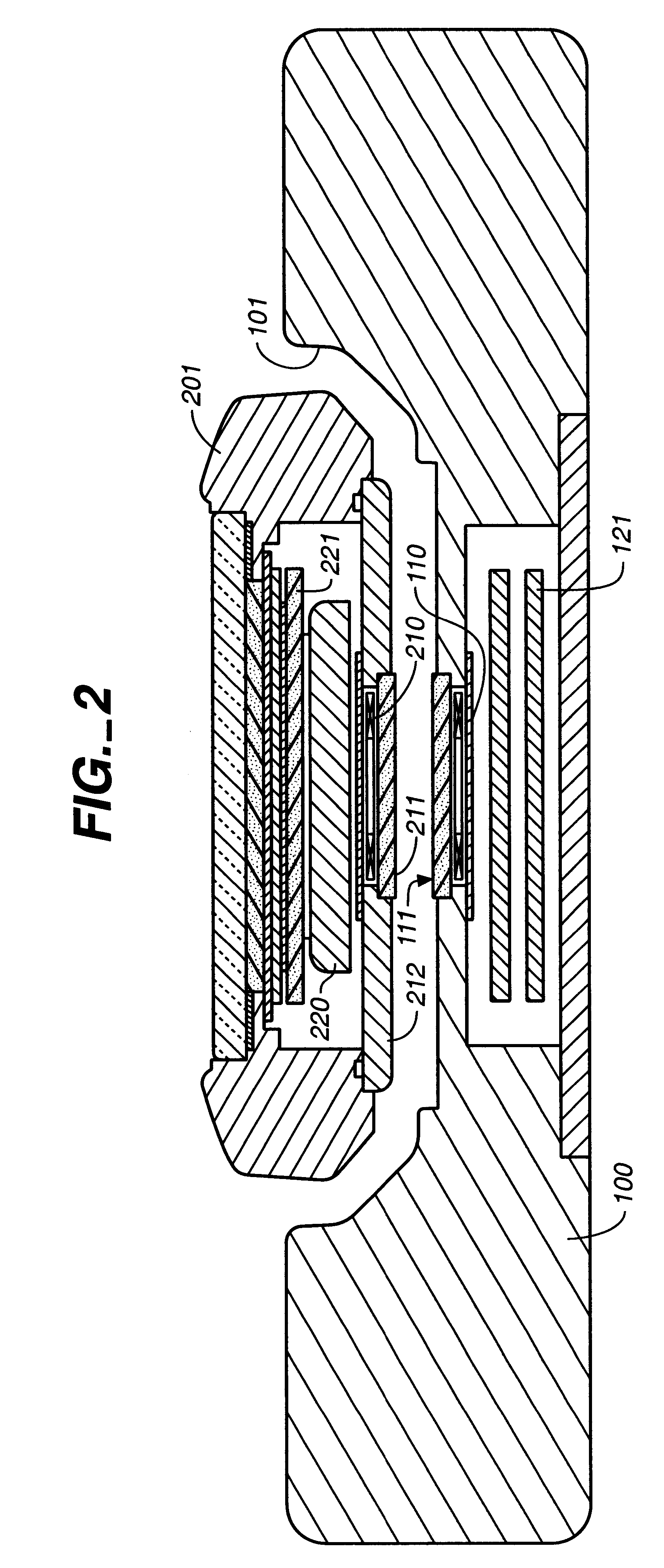
In the first embodiment, the position offset between the station side coil 110 and the watch side coil 210 is detected by comparing the current (charging current) flowing through the watch side coil 210 with the predetermined threshold. As shown in FIG. 15, however, the current flowing through the watch side coil 210 is reduced with an increase in battery voltage of the secondary battery 220. Depending on actual conditions, therefore, it cannot be often determined whether a current reduction is caused by the position offset or a voltage increase of the secondary battery.

In view of the above, this second embodiment intends to more precisely determine the presence of the position offset based on the charging current and the voltage of the secondary battery.

[2.1] Electrical Construction of Electronic Watch

An electronic watch of the second embodiment will now be described with reference to FIG. 16.

Similar components in FIG. 16 to those of the electronic watch of the...

third embodiment

[3] Third Embodiment

A third embodiment of the present invention will now be described.

[3.1] Premise

A manner of deciding the charging time in this third embodiment will be briefly described prior to a detailed description.

First, FIG. 29 is a graph showing a charge / discharge characteristic of a general secondary battery. As shown in FIG. 29, the terminal voltage of the secondary battery is substantially constant in the charge mode. Further, as mentioned above, the terminal voltage of the secondary battery in the charge mode does not represent a true value.

That point is described with reference to FIG. 31. Generally, because a secondary battery has an internal resistance Re, a voltage Evc resulted from adding the product of the internal resistance Re of the secondary battery and a charging current Ei to a true voltage Evd of the secondary battery is detected in the charge mode.

Consider here that the secondary battery is charged with a constant voltage E. In this case, the charging curr...


PUM


Abstract

A first circuit having a first coil electrically charges a second circuit having a second coil through electromagnetic coupling of the two coils. When data signals are to be transferred between the first and second circuits, signal transfer is started only after the second circuit has been charged for a predetermined period of time. The position relationship between the coils is also detected, and a charging/transfer selector changes a duty ratio between charge transfer and data transfer in accordance with the detected result. The charge is transferred in an intermittent manner, and the charging rate is adjusted according to the difference between the voltage of a secondary battery observed during a charging phase and the voltage of the secondary battery observed a certain time after interruption of the charging phase, or vice versa.

Description

The present invention relates to an electronic device and a control method for the electronic device, with which when power or signals are transferred through electromagnetic coupling between coils disposed in opposing positions, a position offset between both the coils, for example, can be detected, and charging and data transfer can be controlled depending on, e.g., the position offset between both the coils. The present invention also relates to an electronic device and a recharge-rate estimating method for a secondary battery, with which a recharge rate of the secondary battery under charging can be estimated with a simple construction, as well as a charging control method for controlling charging of the secondary battery in accordance with an estimated resultRecently, it has been increasingly customary to place a small portable electronic device, such as a portable terminal and an electronic watch, in a charger, which is also called a station, for charging of the electronic dev...

Claims


Application Information

Patent Timeline
IPC IPC(8): G01R31/36G04C10/00H02J7/02H02J7/10
CPCG01R31/3648G04C10/00H02J7/025H02J7/00302H02J50/005H02J7/0044H02J50/80H02J50/90H02J50/10
Inventor HONDA, KATSUYUKIHAYAKAWA, MOTOMUAOSHIMA, ICHIROKOSUDA, TSUKASA
Owner CHAMIRAUX MANAGEMENT LLC
Why Eureka
Try Eureka