

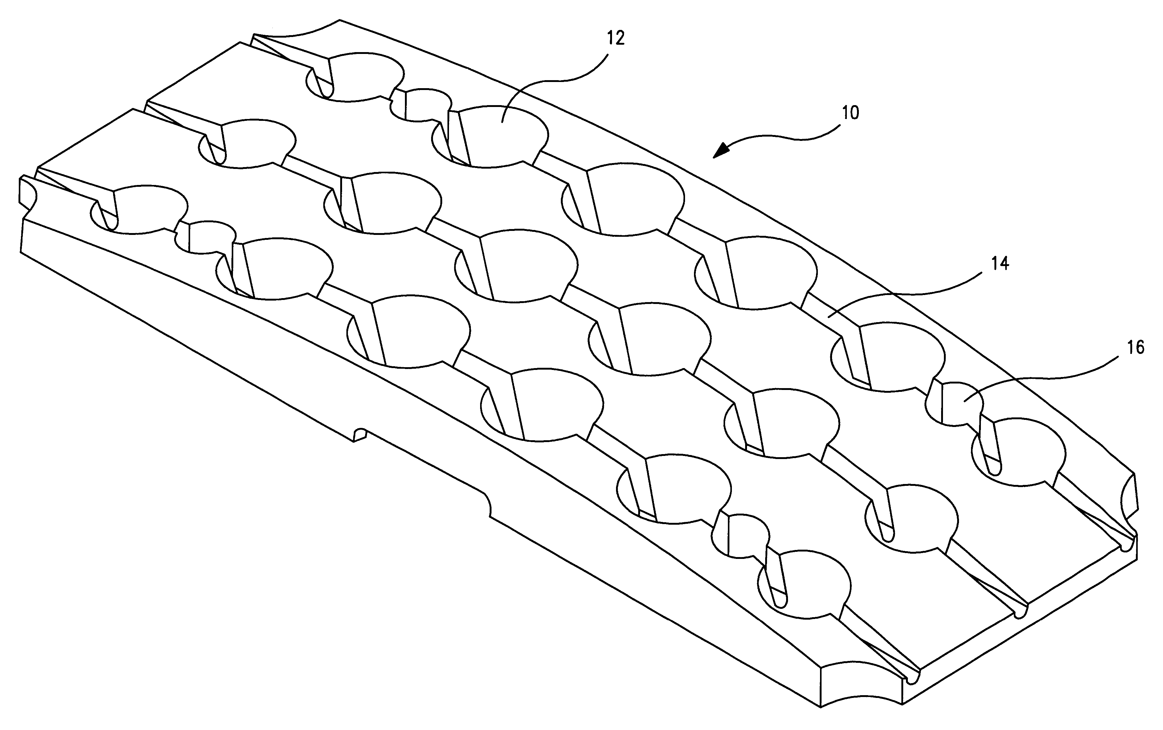
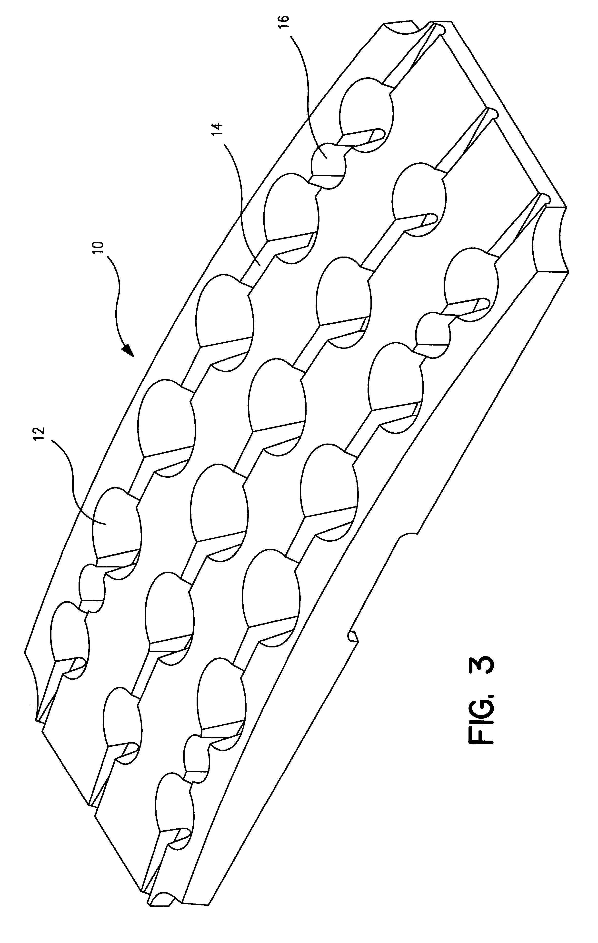
High flux led assembly
a high-flux led and assembly technology, applied in the direction of transportation and packaging, semiconductor devices for light sources, lighting and heating apparatus, etc., can solve the problems of increased possibility of damage resulting from overheating, preventing the application of led arrays to emergency vehicle warning lights, and being susceptible to thermal damag
- Summary
- Abstract
- Description
- Claims
- Application Information
AI Technical Summary
Problems solved by technology
Method used
Image

Examples
Embodiment Construction
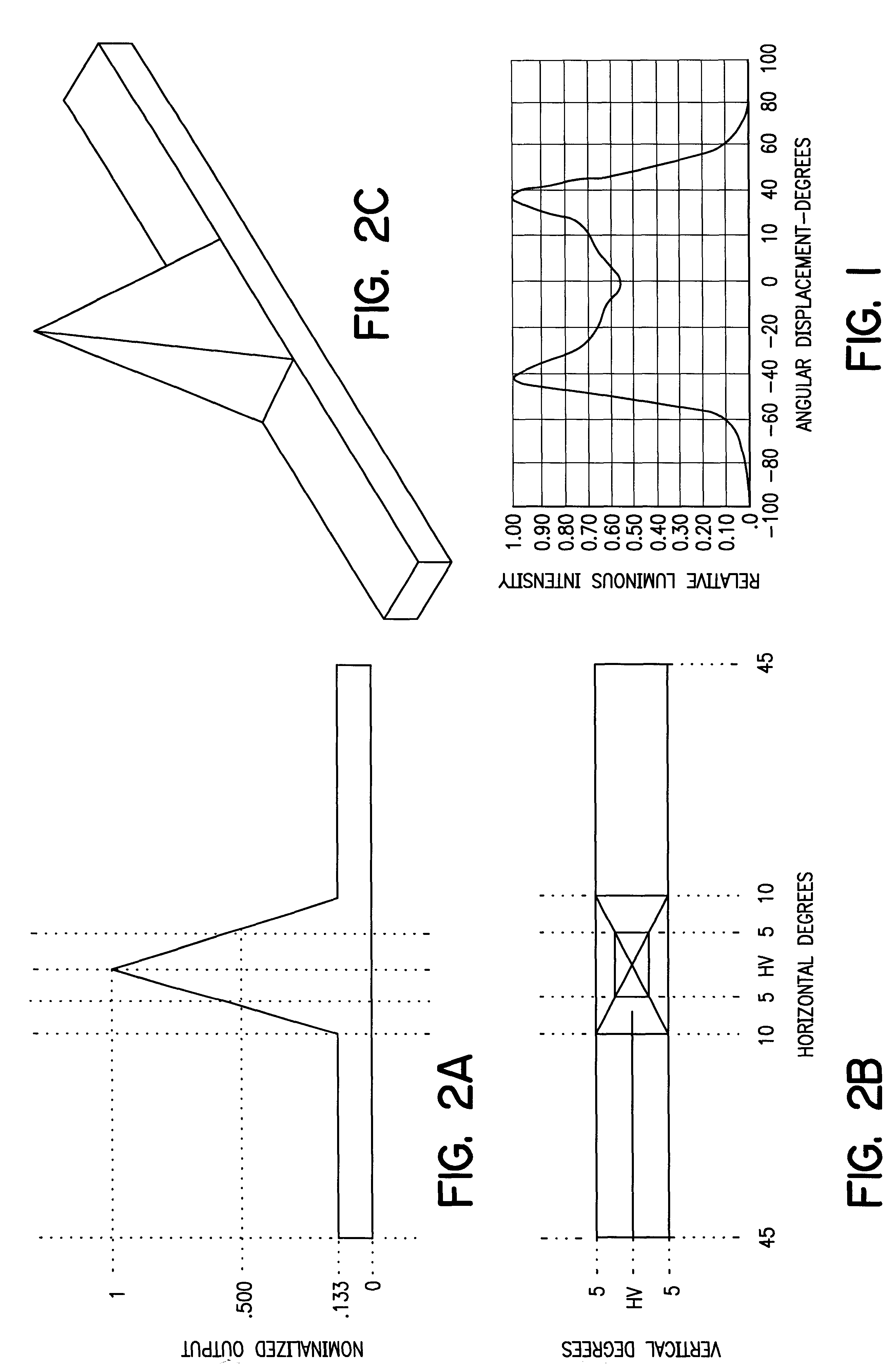
Commercially available LED's have an integral plastic lens which defines an axis. With reference to the drawings, FIG. 1 represents an "M" shaped plot of relative luminous intensity versus angular displacement for a recently introduced high intensity LED. As may be seen from FIG. 1, the light produced by such LED's is concentrated by the integral lens in a ring located approximately 40.degree. off-axis. This condition could be rectified, to provide a light beam having maximum intensity on the axis which passes through the center of the integral lens of the device, through the use of additional optics located in front of the LED, i.e., a second, independent lens. However, such an additional lens would cause substantial attenuation of the emitted light.
To maximize the percentage of the emitted light which will be radiated toward a remote viewer, in the manner to be described below, the present invention achieves the spacial radiation pattern represented in FIG. 2 without interposing a...
PUM
 Abstract
Description
Claims
Application Information